


40
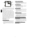
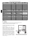
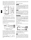
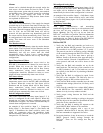
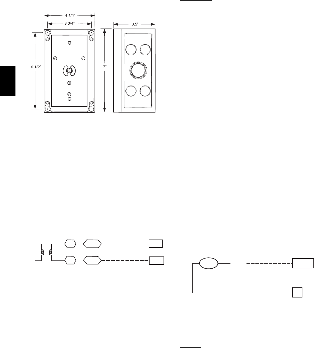
Outdoor Air Quality Sensor (PNO 33ZCSENCO2 plus
weathe rproof enclosure) — The outdoor air CO
2
sensor is
designed to monitor carbon dioxide (CO
2
) levels in the
outside ventilation air and interface with the ventilation
damper in an HVAC system. The OAQ sensor is packaged
with an outdoor cover. See Fig. 60. The outdoor air CO
2
sensor must be located in the economizer outside air hood.
COVER REMOVED SIDE VIEW
C07135
Fig. 60 -- Outdoor Air Quality Sensor Cover
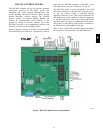
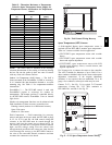
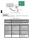
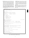
Wiring the Outdoor Air CO
2
Sensor — A dedicated power
supply is required for this sensor. A two--wire cable is
required to wire the dedicated power supply for the sensor.
The two wires should be connected to the power supply
and terminals 1 and 2.
To connect the sensor to the control, identify the positive
(4 to 20 mA) and ground (SIG COM) termina ls on the
OAQ sensor. See Fig. 58. Connect the 4--20 mA terminal
to RTU--MP J4--5. Connect the SIG COM terminal to
RTU--MP J4--6. See Fig. 61.
SEN
COM
J4-5
J4-6
OAQ Sensor/RH Sensor
24 VAC
C08463
Fig. 61 -- RTU--MP / Outdoor CO
2
Sensor
(33Z CSENCO2) Connectio ns
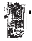
On 548J units equippe d with factory--installed Smoke
Detector(s), the smoke detector controller implements the
unit shut down through i ts NC cont act set connected to the
unit’s CTB input. The FSD function is initiated via the
smoke detector’s Alarm NO contact set. The RTU--MP
controller communicates the smoke detector’s tripped
status to the BAS building control. See Fig. 42 for unit
smoke det ector wiring.
The Fire Shutdown Swi tch c onfiguration,
MENU
→
Config
→
Inputs
→
input 5, identifies the
normally open status of this input when there is no fire
alarm.
Alarm state is reset when the smoke detector alarm
condition is cleared and reset at the smoke detector in the
unit.
Connecting Discrete Inputs
Filter Status
The filter status accessory is a field--installed accessory.
This accessory detects plugge d filters. When installing
this accessory, the unit must be configured for filter status
by setting MENU
→
Config
→
Inputs
→
input3,5,8,or9
to Filter Status and normally open (N/O) or normally
closed (N/C). Input 8 or 9 is recommended for easy of
installation. Refer to Fig. 46, Fig. 47 and Fig. 48 for wire
terminations at J5.
Fan
Status
The fan status accessory is a field--installed accessory.
This accessory detects when t he indoor fan is blowing air.
When installing this accessory, the unit must be
configured for fan status by setting
MENU
→
Config
→
Inputs
→
input3,5,8,or9to Fan
Status and normally open (N/O) or normally closed (N/C).
Input 8 or 9 is recommended for easy of i nstallation. Refer
to Fig. 46, Fig. 47, and Fig. 48 for wire terminati ons at J5.
Remote
Occupancy
The remote occupancy accessory is a field-- installed
accessory. This accessory overrides the unoccupied mode
and puts the unit in occupied mode. When installing this
accessory, the unit must be configured for remote
occupancy by setting MENU
→
Config
→
Inputs
→
input 3,
5, 8, or 9 to Remote Occupancy and normally open (N/O)
or normal ly closed (N/C).
Also set MENU
→
Schedules
→
occupancy source to DI
on/off. Input 8 or 9 is recommended for easy of
installation. Refer to Fig. 46 and Table 14 for wire
terminations at J5.
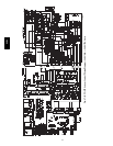
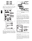
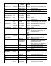
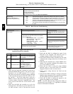
Power Exhaust (output)
Connect the accessory Power Exhaust contactor coil(s) per
Fig. 62.
Power Exhaust
J11-3
C
TAN
GRA
PEC
CTB
THERMOSTAT
C08464
Fig. 62 -- R TU--MP Power Exhaust Connections
Space Relative Humidity Sensor -- The RH sensor is not
used with 548J models at this time.
Communication Wiring -- Protocols
General
Protocols are the communication languages spoken by
control devices. The main purpose of a prot ocol is to
communicate information in the most efficient method
possible. Different protocols exist to provide different
kinds of information for different applications. In the BAS
application, many different protocols are used, depending
548J