


52
TR1
24 Vac
COM
TR
24
Vac
HOT
12
3
4
5
EF
EF1
+
_
P1
T1
P
T
N
EXH
2V 10V
EXH
Set
Set
2V 10V
2V 10V
DCV
DCV
Free
Cool
B
C
A
D
SO+
SR+
SR
SO
AQ1
AQ
DCV
Min
Pos
Open
Max
N1
C06038
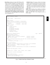
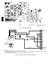
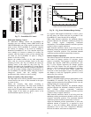
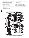
Fig. 77 -- EconoMi$er IV Control
Diff erential Enthalpy Control
For differential enthalpy control, the EconoMi$er IV
controller uses two enthalpy sensors (HH57AC078 and
CRENTDIF004A00), one in the outside air and one in the
return air duct. The EconoMi$er IV controller compares
the outdoor air enthalpy to the return air enthalpy to
determine EconoMi$er IV use. The controll er selects the
lower enthalpy air (return or outdoor) for cooling. For
exam ple, when t he outdoor air has a lower enthalpy than
the return air, the EconoMi$er IV opens to bring in
outdoor ai r for free cooling.
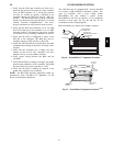
Replace the standard outside air dry bulb temperature
sensor with the accessory enthalpy sensor in the same
mounting location. (See Fig. 66.) Mount the return air
enthalpy sensor in the return air duct. (See Fig. 75.)
Wiring is provided in the EconoMi$e r IV wiring harness.
(See Fig. 66.) The outdoor enthalpy changeover setpoint is
set with the outdoor enthalpy setpoint potentiome ter on
the EconoMi$er IV controller. When using t his mode of
change over cont rol, turn the enthalpy setpoint
potentiometer fully clockwise to the D setting.
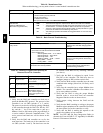
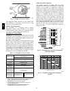
Indoor Air Quality (IAQ) Sensor Input
The IAQ input can be used for demand control ventilation
control based on the level of CO
2
measured in the space
or return air duct.
Mount the accessory IAQ sensor according t o
manufacturer specific ations. The IAQ sensor should be
wired to the AQ and AQ1 terminals of the controller.
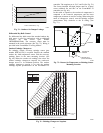
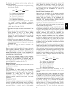
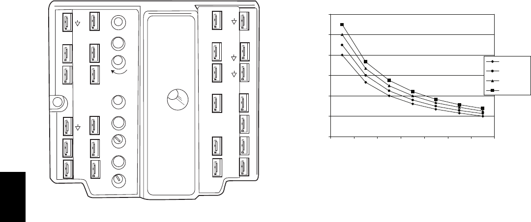
Adjust the DCV potent iometers to correspond t o the DCV
voltage output of the indoor air quality sensor at the
user-determined setpoint. (See Fig. 78.)
0
1000
2000
3000
4000
5000
6000
2345678
800 ppm
900 ppm
1000 ppm
1100 ppm
RANGE CONFIGURATION (ppm)
DAMPER VOLTAGE FOR MAX VENTILATION RATE
CO SENSOR MAX RANGE SETTING
2
C06039
Fig. 78 -- CO
2
Sensor Maximum Range Settings
If a separate field-supplied transformer is used to power
the IAQ sensor, the sensor must not be grounded or the
EconoMi$er IV control board will be damaged.
When using demand ventilation, the minimum damper
position represents the minimum ventilation position for
VOC (volatile organic compounds) ventilation
requirements. The maximum demand ventilation position
is used for fully occupied ventilation.
When demand ventilation control is not being used, the
minimum position potentiometer should be used t o set the
occupied ventilation position. The maximum demand
ventilation position should be t urned fully clockwise.
Exhaust Setpoint Adjustment
The exhaust setpoint will dete rmine when the exhaust fan
runs based on damper position (if accessory power
exhaust is install ed). The setpoint is modified with the
Exhaust Fan Setpoint (EXH SET) potentiometer. (See
Fig. 72.) The setpoint represents the damper position
above which the exhaust fans will be turned on. Whe n
there is a call for exhaust, the EconoMi$er IV controller
provides a 45 ±15 second delay before exhaust fan
activation to allow the dampers to open. This delay allows
the damper to reach the appropriate position to avoid
unnece ssary fa n overload.
Minimum Position Control
There is a minimum damper position potentiometer on the
EconoMi$er IV control ler. (See Fig. 72.) The minimum
damper position maintains the minimum airflow into the
building during t he occupied period.
When using demand ventilation, the minimum damper
position represents the minimum ventilation position for
VOC (volatile organic compound) ventilation
requirements. The maximum demand ventilation position
is used for fully occupied ventilation.
When demand ventilation control is not being used, the
minimum position potentiometer should be used t o set the
occupied ventilation position. The maximum demand
ventilation position should be t urned fully clockwise.
Adjust the minimum position potentiometer to allow the
minimum amount of outdoor air, as required by local
codes, to enter the building. Make minimum position
adjustments with at least 10_F temperature difference
betwee n the outdoor and return-air temperatures.
548J