Instruction 24-9448 6-13
Maintenance
6.7 Pump Replacement
Parts & Tools Required:
Replacement Pump:
Gas Pump P/N 24-1393
Purge Pump P/N 3015-1716
Soldering Iron and Solder
Medium Phillips Screwdriver
Small Flat Blade Screwdriver
Procedure:
1. Gain access to both the gas and purge pumps by removing the rear
case. Refer to Section 6.1.
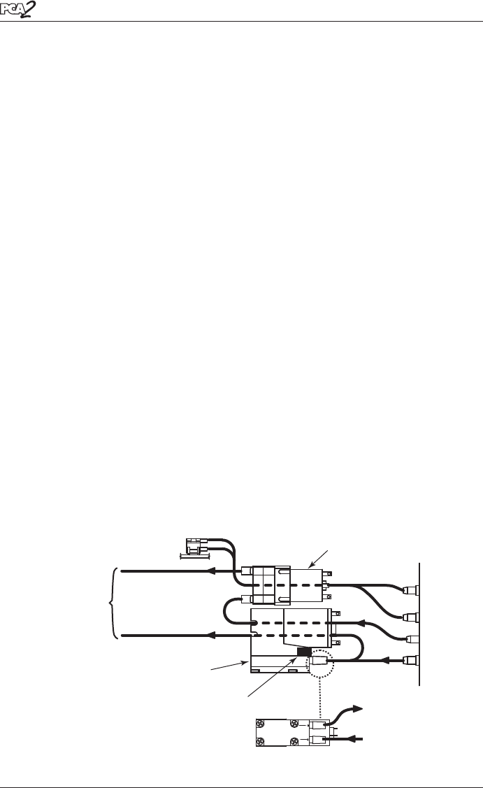
2. Unsolder the red and black wires from pump being replaced. Note that
during installation of the new pump, the red dot on the pump motor
indicates the positive (red wire) connection.
3. Do one of the following:
• Gas Pump Removal: Push pump latch toward bottom of analyzer
and lift gas pump out from its mounting location.
• Purge Pump Removal: Insert a small flat blade screwdriver
between the purge pump motor and the pump chassis, and then pry
the pump out from its mounting location.
4. Remove tubing from pump.
3. Install new pump by reversing this procedure.
•
-
-
•
•
•
–∆P
+∆P
–∆P (Bottom)
+∆P (Top)
PRESSURE
PURGE AIR
GAS
Gas IN
GAS PUMP LATCH
GAS PUMP
PURGE PUMP
Gas OUT
OUTIN
Figure 6-8. Pump Tubing Connections
To Sensors
See Figure 6-3


