


Instruction 24-9448 1-5
Introduction
1.4 Operational Overview
The PCA 2 is powered by either its 4 internal batteries, or by an optional
AC power adapter that operates from any convenient source of 100–
240 VAC, 50/60 Hz power. The type of batteries used can be either dispos-
able alkaline or rechargeable NiMH. Note that rechargeable batteries can
be charged inside the analyzer using the optional AC power adapter.
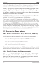
The PCA 2 is controlled by 11 front panel push buttons, while a graphical
LCD is used to display all combustion and emission test data and analyzer
parameters.
A probe and hose assembly, with an integral thermocouple and filter/wa-
ter-trap connect to the bottom of the analyzer, thus providing the means of
drawing in gas samples, and for measuring stack temperature and draft.
The PCA 2 is turned ON by pressing its red I/O button. A warm-up period
of 60 seconds then begins, during which time the analyzer performs self
diagnostics. At the end of the warm-up period, if no errors were detected
the message “NO ERRORS DETECTED” is briefly displayed followed by
the display of the Combustion Test HOLD screen. If errors were detected,
the message “ERRORS DETECTED” is displayed along with a list of the
errors. These errors must be corrected before proceeding with the combus-
tion test.
Before starting a test be sure to select the fuel being burned. The default
fuel selected is Natural Gas. Note that the name of the fuel being burned
is indicated at the top of the display. To change the fuel: first, press the
MENU (F2) button; next, select FUEL from the menu; then use the but-
tons to highlight the fuel being burned; and finally, press the green ENT
button to select the highlighted fuel.
To assure correct combustion-efficiency calculations, the analyzer must
know the burner’s primary-air temperature. The analyzer normally uses
its internal temperature sensor for the primary-air temperature value, but
this method is only acceptable if the burner is using ambient room air. If
the burner is drawing in cold outside air, we recommend that the optional T-
AIR thermocouple be used. This thermocouple plugs into the bottom of the
analyzer and is placed in the burner’s primary-air stream.
Begin the combustion test by first inserting the analyzer’s probe tube into
the stack-gas stream of the appliance under test, and then pressing the
RUN/HOLD button to display the Combustion Test RUN screen. The ana-
lyzer will begin to continuously monitor the stack temperature, %O
2
and