


Instruction 24-94484-6
Operation
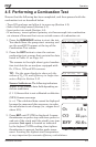
4. You can now begin burner-service procedures. The analyzer readings
will change quickly to show changes in burner performance.
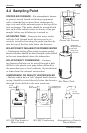
CAUTION: Position the Water Trap with its gas-flow arrow
pointing upward. Do not let water condensate go above the tip
of the riser tube. The sensors could be damaged if water would
enter the analyzer. Empty the Water Trap after every combus-
tion test (refer to Section 4.9)
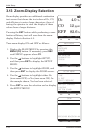
5. Pressing the RUN/HOLD button freezes all readings, stops the pump and
displays the Combustion-Test HOLD screen. Press the ENT button to view
all test values at the moment the RUN/HOLD button was pressed. Press-
ing RUN/HOLD again restarts the pump and resumes testing.
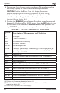
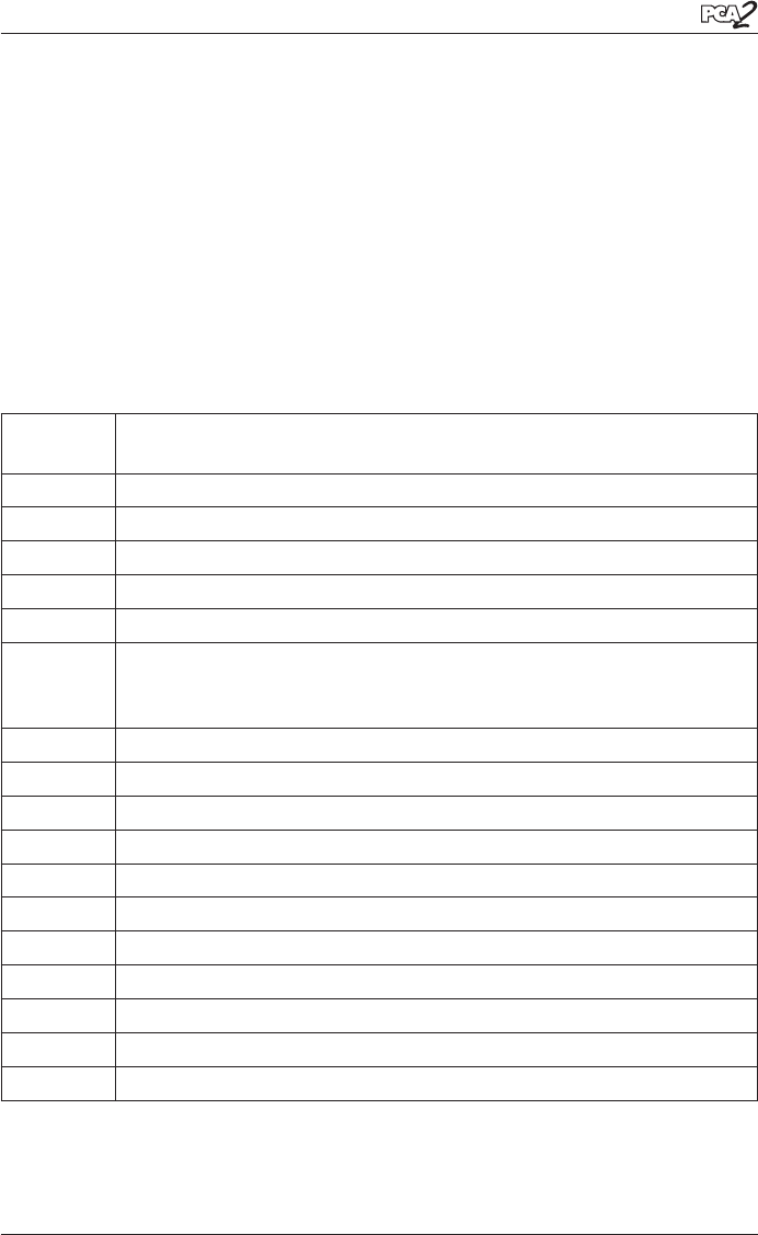
TABLE 4-1. LIST OF COMBUSTION TEST DATA
Display
Name
Description of Measurement or Calculation
O
2
% Oxygen
CO Carbon Monoxide
(1)
EFF % Combustion Efficiency
CO
2
% Carbon Dioxide
T-STK Stack Temperature
T-AIR Primary / Ambient Air Temperature as measured either in-
ternally or by an optional external thermocouple plugged into
the analyzer’s T-AIR connector
EA % Excess Air
CO(n) Carbon Monoxide ppm level referenced to a % of oxygen
(2)
NO Nitric Oxide
(1)
NO
2
Nitrogen Dioxide
(1)
NOx Oxides of Nitrogen (combination of NO and NO
2
)
(1)
SO
2
Sulfur Dioxide
(1)
NO(n) Nitric Oxide ppm level referenced to a % of oxygen
(2)
NO
2
(n) Nitrogen Dioxide ppm level referenced to a % of oxygen
(2)
NOx(n) Oxides of Nitrogen ppm level referenced to a % of oxygen
(2)
SO
2
(n) Sulfur Dioxide ppm level referenced to a % of oxygen
(2)
NO Temp Nitric Oxide Sensor Temperature (3)
(1) Pollution unit of measure selected per Section 3.8
(2) The letter “n” represents the oxygen reference level of between 0 and 15% as
selected per section 3.11
(3) Shown only on printout, not on LCD display.