Instruction 24-9448 3-3
Initial Setup
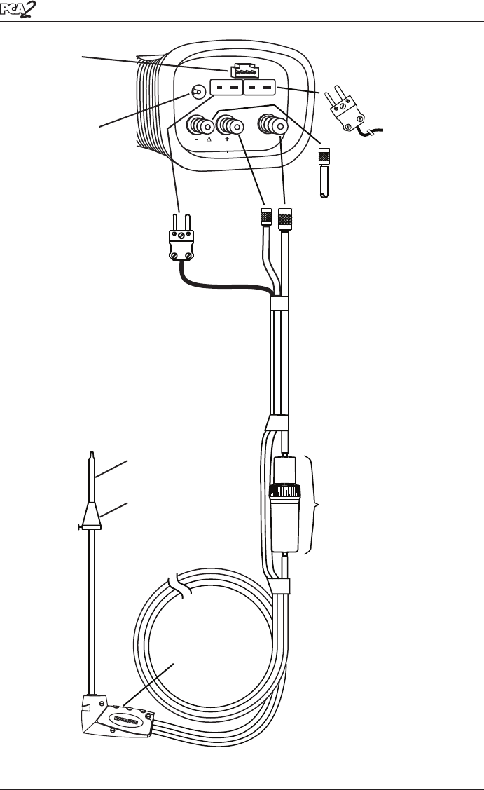
Figure 3-2. Connecting the Probe and Hose Assembly to the PCA 2
POWER
P
T-STACK T-AIR
GAS
Differential
Pressure Hose
(— ∆P) (Optional)
Probe
Handle
Water Trap /
Filter Assembly
Stack Gas
Thermocouple
Connector
(T-STACK)
AC Power
Adapter Jack
(POWER)
Option
Connector
(Optional External
Measurement)
Draft
Hose
(+ ∆P)
Gas Sample
Hose
(GAS)
Probe Tube
Probe Stop
Primary /
Ambient Air
Thermocouple
(T-AIR) (Optional)


