


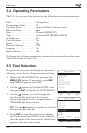
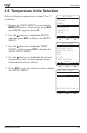

Instruction 24-94483-2
Initial Setup
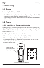
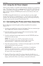
3.2.2 Using the AC Power Adapter
The AC power adapter is capable of powering the analyzer on a continuous
basis. The adapter plugs into an appropriate 100–240 VAC, 50/60 Hz wall
outlet, and produces an output of +9 VDC. The adapter’s output connector
plugs into the analyzer’s POWER jack located on the bottom of the unit
(Figure 3-2).
If NiMH rechargeable batteries are used, the adapter can also rapid
charge these batteries in approximately 2 - 3 hours while still inside the
analyzer. For the batteries to be charged, however, the analyzer’s battery
charger circuit must be turned ON per Section 3.14.
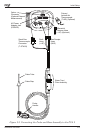
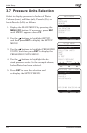
3.3 Connecting the Probe and Hose Assembly
Do the following to attach the probe and hose assembly to the analyzer
(Figure 3-2):
1. Push the gas-sample hose connector, the larger of the two connectors (giv-
ing a slight twist), onto the analyzer’s GAS fitting.
2. Push the draft-hose connector, the smaller connector (giving a slight
twist), onto the analyzer’s +∆P fitting.
3. Push the stack-gas thermocouple connector into the T-STACK jack (con-
nector fits in only one way).
NOTE: The analyzer has a built-in temperature sensor for
measuring ambient temperature. Perform Step 4 only if the
optional primary / ambient air thermocouple is used.
4. Push the optional primary / ambient air thermocouple into the T-AIR
jack (connector fits in only one way).
IMPORTANT: To assure the accurate calculation of combustion
efficiency, the optional primary / ambient air thermocouple
must be used when the burner’s primary-air temperature is not
the same as the room temperature.
5. Inspect all hoses for cracks. If any hose is found to be defective, re-
place the entire probe and hose assembly. Check that the water trap is
empty, and that the filter is not dirty or saturated with water.