


92 SS-SVX09A-EN
System Start-Up
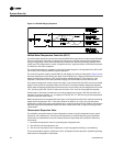
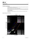
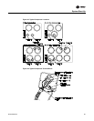
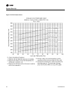
11. After the compressors and condenser fans for the operating circuit have been operating for
approximately 30 minutes, observe the operating pressures. Use the appropriate pressure
curve in
Figure 47 to determine the proper operating pressures. If the operating pressures
indicate a refrigerant shortage, measure the system superheat and system subcooling.
Note: Do Not release refrigerant to the atmosphere! If adding or removing refrigerant is required,
the service technician must comply with all Federal, State and local laws. Refer to general
service bulletin MSCU-SB-1 (latest edition).
Subcooling
The outdoor ambient temperature must be between 65ºF and 105ºF and the relative humidity of the
air entering the evaporator must be above 40 percent. When the temperatures are outside of these
ranges, measuring the operating pressures can be meaningless.
With the unit operating at “Full Circuit Capacity”, acceptable subcooling ranges between 14ºF to
22ºF.
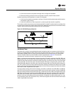
Measuring Subcooling
a. At the liquid line service valve, measure the liquid line pressure. Using a Refrigerant 22
pressure/temperature chart, convert the pressure reading into the corresponding saturated
temperature.
b. Measure the actual liquid line temperature as close to the liquid line service valve as
possible. To ensure an accurate reading, clean the line thoroughly where the temperature
sensor will be attached. After securing the sensor to the line, insulate the sensor and line to
isolate it from the ambient air.
Note: Glass thermometers do not have sufficient contact area to give an accurate reading.
c. Determine the system subcooling by subtracting the actual liquid line temperature
(measured in b) from the saturated liquid temperature (converted in a).
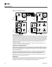
Measuring Superheat
d. Measure the suction pressure at the outlet of the evaporator as close to the expansion valve
bulb location as possible.
e. Measured the suction line temperature as close to the expansion valve bulb, as possible.
f. Using a Refrigerant/Temperature chart, convert the pressure reading to a corresponding
saturated vapor temperature.
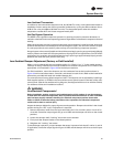
Note: On many Trane fan/coil units, an access valve is provided close to the expansion valve bulb
location. This valve must be added on climate changers and other evaporators.
g. Subtract the saturated vapor temperature (converted in c), from the actual suction line
temperature (measured in b). The difference between the two temperatures is known as
“superheat”.
12. Verify that the oil level in each compressor is correct. The oil level may be down to the bottom
of the sight glass but should never be above the sight glass.
13. Once the checks and adjustments for the operating circuit has been completed, check and
record the:
ambient temperature;
compressor oil level (each circuit);
compressor suction and discharge pressures (each circuit);
superheat and subcooling (each circuit);
Record this data on an “operator’s maintenance log” shown in Table 18. Repeat these procedures
for the second refrigeration circuit, if applicable.