


SS-SVX09A-EN 89
System Start-Up
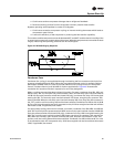
“Air Over” Evaporator Application
Verifying Proper Supply Fan Rotation
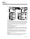
1. Ensure that the “System” selection switch at the remote panel is in the “Off” position and the
“Fan” selection switch for the appropriate controls application is in the “Auto” position. (VAV
units do not utilize a “Fan” selection input.)
2. Turn the main power disconnect switch or circuit protector switch for the unit to the “On”
position.
3. Turn the 115 volt control circuit switch 1S2 to the “On” position.
ƽ WARNING
Rotating Components!
Verifying proper components rotation exposes you to rotating components. Have a qualified or
licensed service individual who has been properly trained in handling exposed rotating
components, perform this task. Failure to follow all safety precautions when exposed to rotating
components could result in death or serious injury.
4. Turn the field provided disconnect switch for the supply fan to the “On” position and “bump”
the field supplied control circuit switch “On”, (i.e., “On” then immediately “Off”).
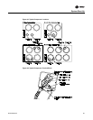
5. While the fan is coasting down, check the rotation. If the fan is rotating backwards, turn the field
provided disconnect switch for the air handler to the “Off” position and interchange any two of
the main power wires at the fan motor starter or contactor.
6. After all adjustments have been made, restart the supply fan and proceed through the following
procedures.
System Airflow Measurement
Much of the systems performance and reliability is closely associated with, and dependent upon
having the proper airflow supplied both to the space that is being conditioned and across the
evaporator coil.
With the supply fan rotating in the proper direction, measure the amperage at the supply fan
contactor. If the amperage exceeds the motor nameplate value, the static pressure is less than
design and the airflow is too high. If the amperage is below the motor nameplate value, static
pressure may be too high and CFM may be too low. To determine the actual CFM (± 5%);
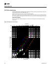
a. Measure the actual fan RPM
b. Calculate the Theoretical BHP
i. (Actual Motor Amps X Motor HP)/Motor Nameplate Amps
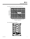
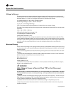
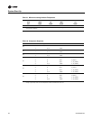
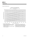
c. Plot this data onto the appropriate Fan Performance Curve or Performance Table that
shipped with the Air Handling equipment. Where the two points intersect, read the CFM line.
Use this data to assist in calculating a new fan drive if the CFM is not at design specifications.
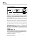
An alternate method with less accuracy is to measure the static pressure drop across the
evaporator coil. This can be accomplished by;
1. Drilling a small hole through the unit casing on each side of the coil.
NOTICE
Coil damage can occur if care is not taken when drilling holes in this area.
2. Measure the difference between the pressures at both locations.