


74 SS-SVX09A-EN
System Pre-Start Procedures
Discharge Air Sensor Checkout (Honeywell Sensor)
ƽ WARNING
Hazardous Voltage!
Disconnect all electric power, including remote disconnects before servicing. Follow proper
lockout/tagout procedures to ensure the power can not be inadvertently energized. Failure to
disconnect power before servicing could result in death or serious injury.
1. Verify that the main power disconnect switch and the control circuit switch 1S2, in the unit
control panel, is “OFF”.
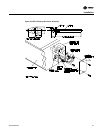
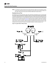
2. At the Discharge Air Controller, in the unit control panel, disconnect the wire connected to
Terminal T1. Use a digital ohmmeter to measure the resistance across Terminal T and the wire
removed from Terminal T1.
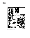
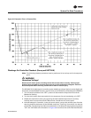
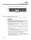
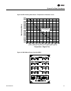
3. Use the conversion chart in Figure 37 to convert the measured resistance to an equivalent
temperature.
4. Measure the actual temperature at the sensor location. If the measured resistance in step 2 is
not within ± 10.0 ohms of the actual temperature, the sensor is out of range; replace it.
Note: Before condemning the sensor, verify that the connecting cable resistance is not excessive.
Refer to the “Field Installed Control Wiring” section.
5. Make all necessary repairs and reconnect the duct sensor lead to terminal T1 on the controller.
6. Restore power to the system and turn all control switches to the “ON” position.
Economizer Actuator Checkout
(w/ “Zone” or “Discharge Air” Temp Controller)
The following procedures should be used to verify that the field provided economizer actuator(s)
function properly. These procedures are based on using a typical Honeywell actuator. If another
type actuator is used, refer to the specific checkout procedures for that actuator.
ƽ WARNING
Hazardous Voltage!
Disconnect all electric power, including remote disconnects before servicing. Follow proper
lockout/tagout procedures to ensure the power can not be inadvertently energized. Failure to
disconnect power before servicing could result in death or serious injury.
1. Turn all control switches to the “Off” position to deactivate the Evaporator Fan and the
Mechanical Cooling. Verify that the main power disconnect switch for the condensing unit and
the control circuit switch 1S2, in the unit control panel, is “OFF”.
2. Verify that the field provided disconnect switch and/or the control circuit switch for the
economizer actuator(s) is “OFF”.
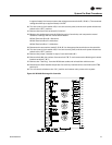
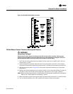
3. At the actuator, disconnect the control wires connected to Terminals W, R, B, and Y.
4. Install a jumper across the actuator terminals R-to-W-to-B.
5. Close the field provided disconnect switch and/or the control circuit switch for the economizer
actuator(s). If the economizer actuator is working properly, it should drive to mid-position.
6. Open the field provided disconnect switch and/or the control circuit switch for the economizer
actuator(s) and remove the jumpers installed in step 4.
7. Reconnect the control wires to the actuator terminals W, R, B, and Y.
8. Restore power to the actuator circuit and turn all control switches to the “ON” position and
restore power to the system.