


SS-SVX09A-EN 47
Installation
Power Wire Sizing and Protection Device
Equations
To correctly size the main power wiring for the unit, use the appropriate calculation(s) listed below.
Read the load definitions that follow and use Calculation #1 for determining the MCA (Minimum
Circuit Ampacity), MOP (Maximum Over current Protection), and RDE (Recommended Dual
Element fuse size) for each unit. Use Calculation #2 to determine the DSS (Disconnect Switch Size)
for each unit.
Load Definitions:
LOAD 1 = CURRENT OF THE LARGEST MOTOR (COMPRESSOR OR FAN MOTOR)
LOAD 2 = SUM OF THE CURRENTS OF ALL REMAINING MOTORS
LOAD 4 = CONTROL POWER TRANSFORMER
= AND ANY OTHER LOAD RATED AT 1 AMP OR MORE
Calculation #1
(MCA, MOP, and RDE)
MCA = (1.25 x LOAD 1) + LOAD 2 + LOAD 4 MOP = (2.25 x LOAD 1) + LOAD 2 + LOAD 4
Select a fuse rating equal to the MOP value. If the MOP value does not equal a standard fuse size
as listed in NEC 240 - 6, select the next lower standard fuse rating.
Note: If selected MOP is less than the MCA, then select the lowest standard maximum fuse size
which is equal to or larger than the MCA, provided the selected fuse size does not exceed
800 amps.
RDE = (1.5 x LOAD 1) + LOAD 2 + LOAD 4
Select a fuse rating equal to the RDE value. If the RDE value does not equal a standard fuse size as
listed in NEC 240 - 6 select the next higher standard fuse rating.
Note: If the selected RDE is greater than the selected MOP value, then select the RDE value to equal
the MOP value.
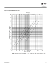
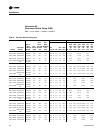
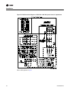
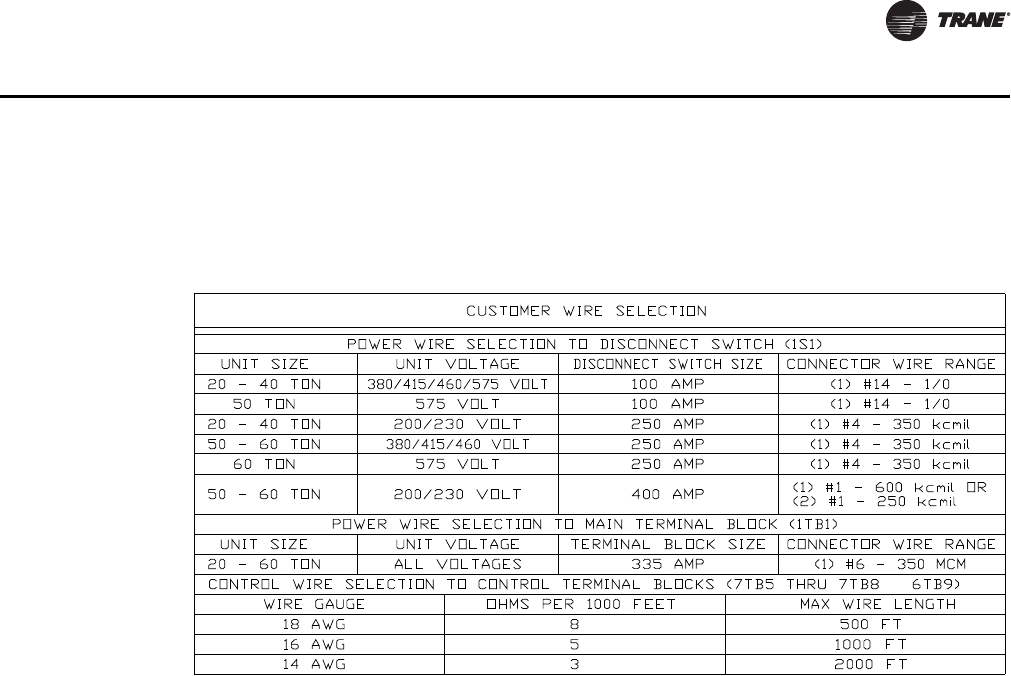
Table 7. Customer Connection Wire Range