


SS-SVX09A-EN 35
Installation
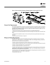
Liquid Line Piping
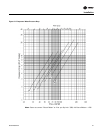
Liquid line sizes are based on their ability to provide a minimum of 5 degrees F (2.7ºC) of sub-
cooling at the expansion valve throughout the unit’s operating system. Increasing the liquid line
size does not increase the available sub-cooling. The uniform liquid line size, pre-selected in the
Table below, are independent of the line length or rise within the permissible guidelines to maintain
this minimum required 5 degree F (2.7ºC) sub-cooling at the expansion valve for a properly charged
RAUC unit operating in a normal air conditioning application.
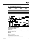
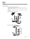
The liquid line should have a slight slope in the direction of flow so that it can be routed with the
suction line.
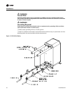
The unit has a liquid line check valve that prevents liquid refrigerant from flowing backward through
the liquid line, filling the condenser, and overflowing to the compressor during the “Off” cycle. A
relief valve is also installed to prevent the build up of high pressure in the liquid line when the unit
is off. For proper operation of the relief valve, the liquid line service valve should not be in the back
seated position but cracked open so the relief valve (and the fan pressure switch) is open to the
condenser. The line that connects the outlet of the 235 psig relief valve to the liquid line service
valve must not be removed.
For more information, refer to the latest edition of Application Guide SS-APG001-EN.
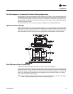
1. Avoid putting liquid lines underground.
2. Route liquid lines as short and direct as possible.
3. Slope liquid lines away form the condensing unit 1-inch for every 10 feet.
4. Only insulate liquid lines that pass through heated areas.
5. Wire solenoid valves according to the field connection diagram for proper pump down
operation.
6. The liquid line filter drier should be as close to the solenoid valve as possible.
Note: If the liquid line riser exceeds 10 feet, refer to Tube Size and Component Selection,
publication number SS-APG001-EN
Liquid Line Interconnecting Tubing
Capacity OD Horizontal (Per Circuit)
OD Vertical
(Per Circuit)
20 Ton 5/8” 5/8”
25 Ton 7/8” 7/8”
30 Ton 7/8” 7/8”
40 Ton 5/8” 5/8”
50 Ton 7/8” 7/8”
60 Ton 7/8” 7/8”
Note: If risers exceed 10 feet, refer to Tube Size and Component Selection, publication number SS-APG001-EN