


42 SS-SVX09A-EN
Installation
Air Vents
Vents must be installed at high points in the piping system to facilitate air purging during the filling
process.
Water Pressure Gauges
Install pressure gauge(s) to monitor the entering and leaving chilled water pressure.
NOTICE
To prevent evaporator damage, do not exceed 150 psig evaporator pressure.
Water Shutoff Valves
Provide shutoff valves in the “Supply” and “Return” pipe near the chiller so the gauge(s),
thermostats, sensors, strainer, etc., can be isolated during service.
Pipe Unions
Use pipe unions to simplify disassembly for system service. Use vibration eliminators to prevent
transmitting vibrations through the water lines.
Thermometers
Install thermometers in the lines to monitor the evaporator entering and leaving water
temperatures.
Balancing Valves
Install a balancing cock (valve) in the leaving water line. It will be used to establish a balanced flow.
Note: Both the entering and leaving water lines should have shutoff valves installed to isolate the
evaporator for service.
Strainer
Install a pipe strainer in the water return line to protect the components from entrapped debris.
Chiller Drain
The chiller drain should be piped to a suitable drain facility to facilitate evaporator draining during
service or shutdown procedures. Provide a shutoff valve in the drain line.
Note: The BPHE chiller does not include a drain plug. Drain piping and shutoff valve must be
installed at the lowest point in the water piping to insure proper draining of the chiller. Insure
that the drain is closed before filling system with water.
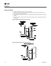
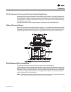
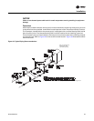
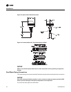
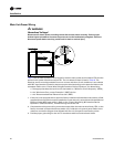
Chiller Flow Switch
Install a flow switch or other flow sensing device, illustrated in Figure 23, to prevent or stop the
compressor operation if the water flow drops off drastically. A flow switch ships with a each unit
when a “T” is included in the miscellaneous digit of the model number. Locate the device in the
chilled water supply line (water outlet) as shown in Figure 22. Refer to the field wiring and unit
schematics for the flow switch electrical interlock connections.
Water Temperature Sensor
The Temperature Sensor and Sensor-well must be installed in the leaving water piping as close to
the chiller as possible. Both devices are located inside the remote panel. Thermal paste is also
provided inside the remote panel and must be used when installing the sensor into the sensor-well.
Refer to Figure 22 for the recommended location. Figure 24 illustrates the Sensor-well dimensions.