


26 SS-SVX09A-EN
Installation
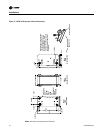
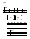
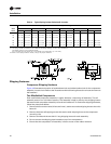
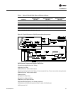
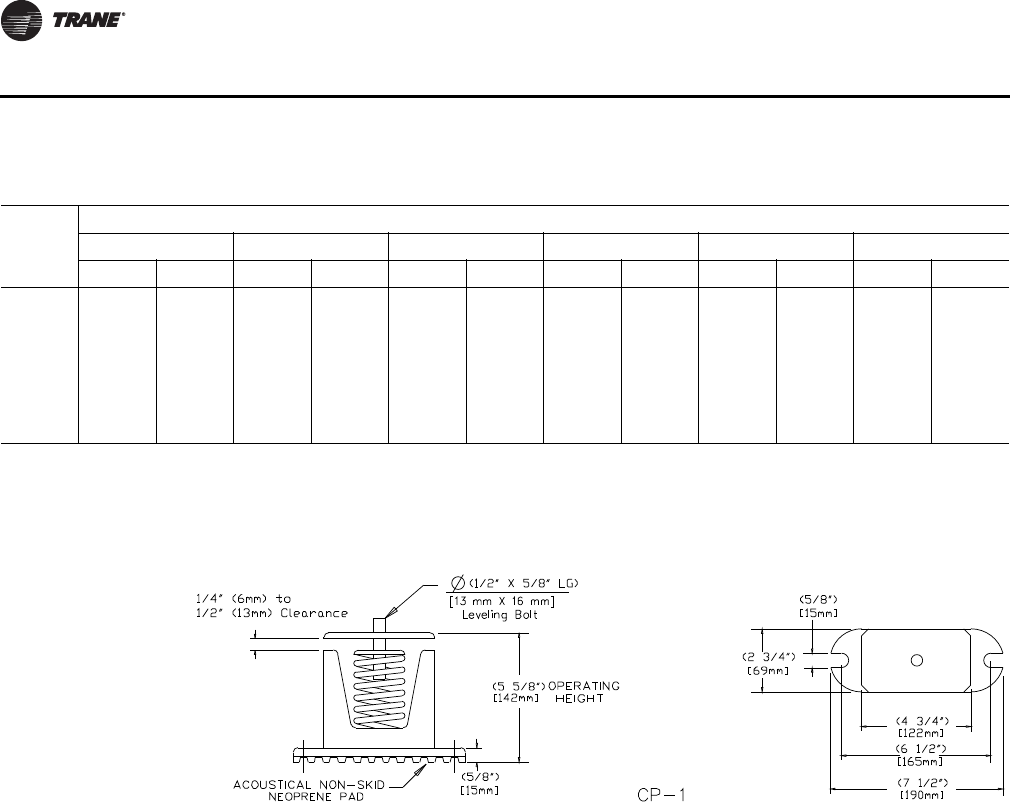
Table 4. Typical Spring Isolator Selection & Location
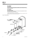
Shipping Fasteners
Compressor Shipping Hardware
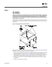
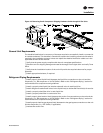
Figure 16 illustrates the location of each tiedown bolt and rubber isolator bolt for the compressor
assembly in each circuit. Refer to the illustration and the following discussion to locate and remove
the fasteners.
Two Manifolded Compressors
Each manifolded compressor assembly is rigidly bolted to a mounting rail assembly. The rail
assembly sets on four (4) rubber isolators. The assembly is held in place by two shipping braces
that secure each compressor assembly rail to the unit’s base rail. To remove the shipping hardware,
follow the procedures below:
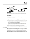
1. Remove the four anchor bolts (2 front and 2 rear), used to secure the shipping brace to the unit’s
base rail.
2. Remove the three self-tapping screws that secure each shipping brace to the compressor
mounting rails.
3. Remove and discard the two 30-1/2" long shipping braces for each assembly.
4. Do not remove the shipping plate located on top of the compressors.
5. Ensure that the compressor rail assembly is free to move on the rubber isolators.
Unit
Tons
Spring Isolator Part Number @ Mounting Location
Location 1 Location 2 Location 3 Location 4 Location 5 Location 6
Al Cu Al Cu Al Cu Al Cu Al Cu Al Cu
20 CP-1-27 CP-1-28 CP-1-26 CP-1-27 CP-1-26 CP-1-26 CP-1-25 CP-1-26
25 CP-1-28 CP-1-28 CP-1-27 CP-1-27 CP-1-26 CP-1-27 CP-1-25 CP-1-26
30 CP-1-28 CP-1-31 CP-1-31 CP-1-31 CP-1-25 CP-1-26 CP-1-26 CP-1-26
40 CP-1-27 CP-1-27 CP-1-27 CP-1-27 CP-1-27 CP-1-28 CP-1-27 CP-1-27 CP-1-27 CP-1-28 CP-1-27 CP-1-27
50 CP-1-28 CP-1-31 CP-1-28 CP-1-28 CP-1-28 CP-1-28 CP-1-27 CP-1-28 CP-1-27 CP-1-28 CP-1-27 CP-1-28
60 CP-1-31 CP-1-31 CP-1-28 CP-1-31 CP-1-28 CP-1-31 CP-1-28 CP-1-31 CP-1-28 CP-1-31 CP-1-27 CP-1-28
1. Mounting locations correlate with those shown in point loading illustration.
2. The spring number is marked on the outside of the spring housing, i.e. CP-1-25 is marked 25.
The isolator spring is color coded as follows;
CP-1-25=Red, CP-1-26=Purple, CP-1-27=Orange, CP-1-28=Green, Cp-1-31=Gray
3. Refer to the “Spring Isolator” section, step 4, for proper clearance.