


SS-SVX09A-EN 63
Installation
Constant Volume Control (Honeywell 973)
The descriptions of the following basic input devices used with the Honeywell 973 Master Energy
Controller (MEC) are to acquaint the operator with their function as they interface with the
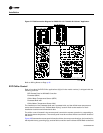
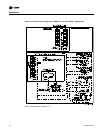
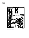
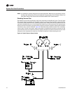
controller. Refer to the field connection diagram in Figure 32 for the specific component
connections at the unit’s control panel.
Electronic Zone Thermostat (Honeywell T7067)
Each unit ordered with constant volume controls (digit 9 in the model number) is shipped with a
Honeywell T7067 electronic zone thermostat. A Honeywell switching subbase (Q667) is also
included. The switching subbase allows the operator to select the “System Mode” of operation, i.e.,
Cool, Heat, Auto, or Off and the “Fan Mode” of operation, i.e., On or Auto.
Note: As long as the status of the system is in an occupied mode, the supply fan will operate
continuously. The fan will only cycle in the “Auto” mode during unoccupied periods.
The zone thermostat should be located in an area with good air circulation to enhance zone
temperature averaging. Position the thermostat about 54" above the floor in a frequently occupied
area.
Do not mount the thermostat where its sensing element may be affected by:
a. Drafts or “dead” spots behind doors or in corners;
b. Hot or cold air from ducts;
c. Radiant heat from the sun, or from appliances;
d. Concealed pipes and chimneys;
e. Vibrating surfaces; or
f. Unconditioned areas behind the thermostat (e.g., outside walls).
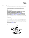
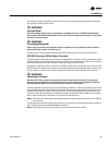
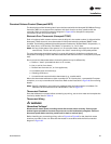
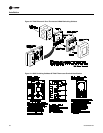
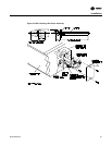
Mount the thermostat subbase on either a standard 2" X 4" handy box, a comparable European
outlet box, or on any nonconductive flat surface. Refer to the illustration in Figure 30 for mounting
details.
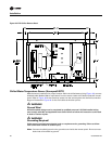
Note: Specific installation instructions are packaged with each thermostat and subbase. For
subbase and thermostat terminal identification, refer to Figure 31.
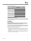
Thermostat Checkout
Once the subbase is mounted, before connecting any wiring, use an ohm meter and complete the
continuity checks listed in Table 11.
Thermostat Wiring
ƽ WARNING
Hazardous Voltage!
Disconnect all electric power, including remote disconnects before servicing. Follow proper
lockout/tagout procedures to ensure the power can not be inadvertently energized. Failure to
disconnect power before servicing could result in death or serious injury.
Before installing any connecting wiring, refer to Figure 3 to Figure 8 for the electrical access
locations provided on the unit. Wire the thermostat in accordance with the field connection
diagram in Figure 32.