


82 SS-SVX09A-EN
System Pre-Start Procedures
Voltage Imbalance
Excessive three phase voltage imbalance between phases will cause motors to overheat and
eventually fail. The maximum allowable voltage imbalance is 2%. Measure and record the voltage
between phases 1, 2, and 3 and calculate the amount of imbalance as follows:
% Voltage Imbalance = 100 X [(AV - VD)/(AV)] where;
AV (Average Voltage) = (Volt 1 + Volt 2 + Volt 3)/3
V1, V2, V3 = Line Voltage Readings
VD = Line Voltage reading that deviates the farthest from the average voltage.
Example: If the voltage readings of the supply power measured 221, 230, and 227, the average volts
would be:
(221 + 230 + 227)/3 = 226 Avg.
VD (reading farthest from average) = 221
The percentage of Imbalance equals:
100 X [(226 - 221)/226)] = 2.2%
The 2.2% imbalance in this example exceeds the maximum allowable imbalance of 2.0%. This
much imbalance between phases can equal as much as a 20% current imbalance with a resulting
increase in motor winding temperatures that will decrease motor life. If the voltage imbalance is
over 2%, notify the proper agencies to correct the voltage problem before operating this
equipment.
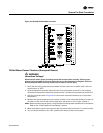
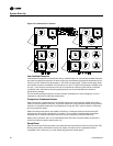
Electrical Phasing
Proper electrical phasing can be quickly determined and corrected before starting the unit by using
an instrument such as an Associated Research Model 45 Phase Sequence Indicator and following
the steps below:
[ ] Turn the field supplied disconnect switch that provides power to terminal block 1TB1 to the “Off”
position.
[ ] Connect the phase sequence indicator leads to the terminal block or to the “Line” side of the
optional factory mounted disconnect switch as follows;
Black (phase A) to L1
Red (phase B) to L2
Yellow (phase C) to L3
[ ] Close the main power disconnect switch or circuit protector switch that provides the supply
power to the condensing unit.
ƽ WARNING
High Voltage is Present at Terminal Block 1TB1 or Unit Disconnect
Switch 1S1.
To prevent injury or death form electrocution, it is the responsibility of the technician to recognize
this hazard and use extreme care when performing service procedures with the electrical power
energized.
[ ] Observe the ABC and CBA phase indicator lights on the face of the sequencer. The ABC indicator
light will glow if the phase is ABC. If the CBA indicator light glows, open the disconnect switch or
circuit protection switch and reverse any two power wires.
[ ] Restore the main electrical power and recheck the phasing. If the phasing is correct.
[ ] Open the main power disconnect switch or circuit protection switch and remove the phase
sequence indicator.