


SS-SVX09A-EN 31
Installation
Low Voltage Wiring (AC & DC)
ƽ WARNING
Hazardous Voltage!
Disconnect all electric power, including remote disconnects before servicing. Follow proper
lockout/tagout procedures to ensure the power can not be inadvertently energized. Failure to
disconnect power before servicing could result in death or serious injury.
Variable Air Volume (VAV) Units
[ ] Install a field provided remote system control switch to activate the system.
[ ] Connect properly sized wiring from the field provided economizer, if applicable, to the discharge
air controller in the unit control panel.
[ ] Install and connect properly sized wiring from the night setback relay contacts to the proper
termination points inside the unit control panel. Verify the appropriate jumpers have been
removed.
[ ] Install the suction line thermostat onto the suction line. Connect properly sized wiring between
the thermostat and terminal strip 7TB7 in the unit control panel.
[ ] Install the discharge air sensor and wire it to the discharge air controller with shielded cable.
EVP Chiller Units
[ ] Install the appropriate jumpers on the chilled solution temperature controller for hot gas bypass
operation (If applicable). Refer to the control wiring diagram that shipped with the unit for jumper
details.
[ ] Install and connect the chilled solution temperature sensor to the chilled solution temperature
controller with shielded cable.
[ ] Install the proper staging resistor onto the chilled solution temperature controller.
Constant Volume Units
[ ] Install the zone thermostat, with or without switching subbase.
[ ] Connect properly sized control wiring to the proper termination points between the zone
thermostat and the unit control panel.
[ ] Install the discharge air sensor and connect it to the master energy controller (MEC) with shielded
cable.
[ ] Connect properly sized wiring from the field provided economizer, if applicable, to the master
energy controller (MEC) in the unit control panel.
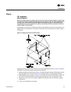
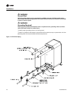
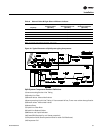
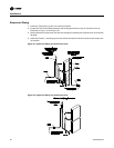
Refrigerant Line Components
Suction line refrigerant components necessary for field installation in the suction line are a filter
(Core Type), access valves (ports), Frostat
TM
control for coil frost protection, and ball shutoff valves.
They are placed in the suction line as illustrated in Figure 18.
The required liquid line refrigerant components include a filter drier (Core Type), access valve(s)
or (ports), solenoid valve(s), moisture indicating sight glass, expansion valve(s), and ball shutoff
valve(s). They are placed in the liquid line as shown in Figure 18.
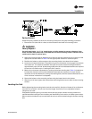
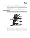
Suction And Liquid Line Filter/Filter Drier (Field Supplied)
Install the filter in the suction line upstream of the compressors. It should be installed so the
canister is at either a 45 or 90 degree angle to prevent oil accumulation.
Install the filter drier in the liquid line as close as possible to the expansion valves. Locate them
upstream of the moisture indicator and solenoid valve.