


SS-SVX09A-EN 75
System Pre-Start Procedures
EVP Chiller Control Checkout (Honeywell W7100G)
Note: The following checkout procedure must be performed in its entirety and in the sequence
given.
ƽ WARNING
Hazardous Voltage!
Disconnect all electric power, including remote disconnects before servicing. Follow proper
lockout/tagout procedures to ensure the power can not be inadvertently energized. Failure to
disconnect power before servicing could result in death or serious injury.
The W7100G (6U11) chilled water controller can be checked out using a highly accurate digital volt-
ohmmeter, the W7100 accessory tool kit (Trane part # TOL-0101 or Honeywell part # 4074EDJ), and
the Honeywell 4074EFV resistor bag assembly.
1. Verify that the main power disconnect switch and the control circuit switch 1S2, in the unit
control panel, is “OFF”.
2. At the unit control panel, unplug the reset relay 1K11 and 1K12, (1K12 used on 40 through 60
Ton units only). Refer to the connection diagram that shipped with the unit for the location of
the relay(s).
3. At the Chilled Water controller (6U11) inside the remote panel, disconnect the sensor (6RT2)
leads form Terminals T & T1.
4. Remove the 3,400 ohm resistor (blue leads) from the test kit and connect it across Terminals T
and T1 to simulate a discharge air temperature of 60ºF.
5. Remove the factory-installed jumper (wire 209A) from the “fast response” Terminals 9 & 10.
6. To simulate a call for maximum reset, remove the jumper from Terminals 6 & 7 and install the
1780 ohm resistor (red leads), from the test kit, across Terminals 6 and 7.
7. Install a jumper across the P1 and P2 Terminals (remote setpoint input).
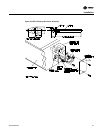
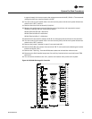
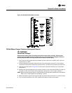
8. Remove the red dust cover from the test plug socket at the bottom of the W7100G. Insert the
“Test Plug”, from the kit, into the test plug socket. The test plug overrides most of the built-in
time delays for staging the compressors “On” and “Off”. Refer to the illustration in
Figure 38 for
terminal and control dial identification.
9. Set the “Reset F” dial at 20ºF and the “Setpoint F” dial at 10ºF
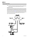
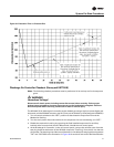
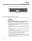
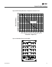
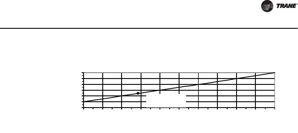
Figure 37. Discharge Duct Sensor 6RT2 & 6RT3 “Temperature vs Resistance” Curve
3000
3200
3400
3600
3800
4000
4200
20 40 60 80 100 120 140 160 180 200 220
Temperature -
O
F (
O
C)
Resistance (Ohms)
(-6.7
o
C) (4.4
o
C) (15.6
o
C) (26.7
o
C) (37.8
o
C) (48.9
o
C) (60.0
o
C) (71.1
o
C) (82.2
o
C) (93.3
o
C) (104.4
o
C)
3483 ± 10 Ohms @
77
O
F (25
O
C)