


SS-SVX09A-EN 79
System Pre-Start Procedures
10. Measure the voltage again across Terminals R (-) and W (+). The measured voltage should now
be approximately 0.2 VDC.
11. Turn the control circuit switch 1S2, in the unit control panel, to the “OFF” position.
12. Remove the wires from Terminals R, B, W, & Y.
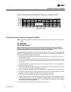
13. Measure the resistance across the following pairs of terminals and compare the actual
resistance readings with the values shown below:
(1) MEC Terminals R-to-W = 226 ohms
(2) MEC Terminals R-to-B = 432 ohms
(3) MEC Terminals R-to-Y = 226 ohms
14. Reconnect the economizer leads W, R, B and Y to the appropriate terminals on the controller.
15. Turn switches 1S2, 5S1, & 5S2 to the “ON” position to restore power to the control system.
Zone Thermostat Checkout (Honeywell T7067)
1. Open the system control switches 5S1 and 5S2 to disable the Evaporator Fan and Heating
system.
2. Close the main power disconnect switch and turn the control circuit switch 1S2, in the unit
control panel, “ON”.
ƽ WARNING
High Voltage is Present at Terminal Block 1TB1 or Unit Disconnect
Switch 1S1.
To prevent injury or death form electrocution, it is the responsibility of the technician to
recognize this hazard and use extreme care when performing service procedures with the
electrical power energized.
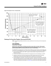
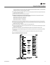
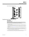
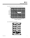
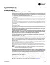
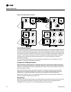
3. At the Zone Thermostat (6U37), use a digital voltmeter to verify that there is 20 volts DC power
between thermostat Terminals 1 & 2. Refer to the illustration in
Figure 31 for terminal
identification. Refer to Table 12 for the thermostat “voltage output” ramps.
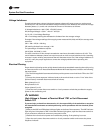
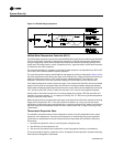
4. To check the “Cooling” output signal, place the voltmeter leads between thermostat Terminals
1 & 4. Refer to
Figure 30 and;
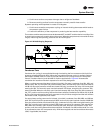
a. move the cooling (blue) setpoint lever from right to left. As the cooling setpoint is lowered,
the voltage signal should increase and the “Cooling” LED brighten.
b. move the cooling (blue) setpoint lever from left to right. As the cooling setpoint rises, the
voltage signal should decrease and the “Cooling” LED dim.
5. To check the “Heating” output signal, place the voltmeter leads between thermostat Terminals
1 & 5. Refer to
Figure 30 and;
a. move the heating (red) setpoint lever from left to right. As the heating setpoint rises, the
voltage signal should increase and the “Heating” LED brighten.
b. move the heating (red) setpoint lever form right to left. As the heating setpoint lowers, the
voltage signal should decrease and the “Heating” LED dim.