


80 SS-SVX09A-EN
System Pre-Start Procedures
Discharge Air Sensor Checkout (Honeywell 6RT1)
ƽ WARNING
Hazardous Voltage!
Disconnect all electric power, including remote disconnects before servicing. Follow proper
lockout/tagout procedures to ensure the power can not be inadvertently energized. Failure to
disconnect power before servicing could result in death or serious injury.
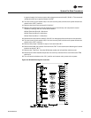
1. Turn the control circuit switch 1S2, in the unit control panel, to the “OFF” position.
2. At the Master Energy Controller, disconnect the wire connected to Terminal T1. Use a digital
ohmmeter to measure the resistance between Terminal T and the wire removed from Terminal
T1.
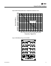
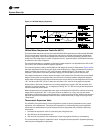
3. Use the conversion chart in Figure 37 to convert the measured resistance to an equivalent
temperature.
4. Measure the actual temperature at the sensor location. If the measured resistance in step 2 is
not within ± 10.0 ohms of the actual temperature, the 6RT1 is out of range; replace it.
Note: Before condemning the sensor, verify that the connecting cable resistance is not excessive.
Refer to the “Field Installed Control Wiring” section.
5. Make all necessary repairs and reconnect the duct sensor lead to terminal T1 on the controller.
6. Turn switches 1S2, 5S1, & 5S2 to the “ON” position to restore power to the control system.
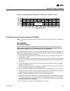
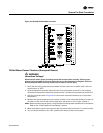
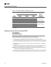
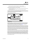
Table 12. Zone Thermostat (6U37) “Voltage Output” ramps
1U11
Function
Nominal Operating Points and Throtting Ranges
Measured
between
these 1U11
Terminals
Pull-In
Voltage*
Drop-Out
Voltage
Throtting
Range
HEAT 1 4.63 VDC 4.0 VDC
HEAT 2 5.88 VDC 5.25 VDC
Terminal 5 (heating)
&
Terminal 1 (common)
HEAT 3 7.13 VDC 6.50 VDC
HEAT 4 8.38 VDC 7.75 VDC
COOL 1 4.58 - 5.42 VDC 3.44 - 4.56 VDC
Terminal 4 (cooling)
&
Terminal 1 (common)
COOL 2 5.43 - 6.34 VDC 4.69 - 5.81 VDC
COOL 3 6.63 - 7.63 VDC 5.90 - 7.10 VDC
COOL 4 7.84 - 8.92 VDC 7.11 - 8.39 VDC
Economizer 2.75 - 4.00 VDC
* "Pull-In" and "Drop-Out" valves are ± 0.25 VDC
** If Applicable