


SS-SVX09A-EN 59
Installation
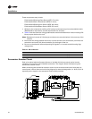
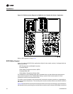
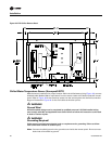
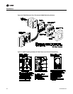
connection diagram illustrated in Figure 29 for the interconnecting points between the remote
panel and the unit’s control panel.
ƽ WARNING
Ground Wire!
All field-installed wiring must be completed by qualified personnel. All field-installed wiring
must comply with NEC and applicable local codes. Failure to follow this instruction could result
in death or serious injuries.
ƽ WARNING
Grounding Required!
Follow proper local and state electrical code on requirements for grounding. Failure to follow
code could result in death or serious injury.
A ground wire must be installed between the EVP remote panel and the unit control panel.
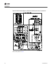
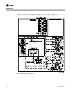
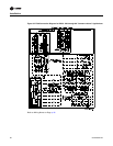
W7100G Discharge Chilled Water Controller
The discharge chilled water controller (6U11) is shipped from the factory with a combination wire/
resistor type jumper installed across Terminals 6, 7, & 8. The resistive portion of the jumper is across
Terminals 7 & 8, which set the number of operating stages, of the control.
As shipped, a 200 ohm resistive jumper is installed across Terminals 7 & 8 on the controller. The
200 ohm resistive jumper is required for two (2) stage operation on 20 through 30 Ton units. If the
unit is a 20, 25, or 30 Ton unit, locate the bag that is secured to the controller, and discard it.
ƽ WARNING
Hazardous Voltage!
Disconnect all electric power, including remote disconnects before servicing. Follow proper
lockout/tagout procedures to ensure the power can not be inadvertently energized. Failure to
disconnect power before servicing could result in death or serious injury.
For 40 through 60 Ton units, requiring four (4) stages of operation, a 402 ohm resistive jumper must
be installed across Terminals 7 & 8 on the controller. Remove the combination wire/resistor jumper
containing the 200 ohm resistor from Terminals 6, 7, & 8. Locate the bag that is secured to the
controller, and install the 402 ohm combination jumper across Terminals 6, 7, & 8 on the controller.
Refer to the remote panel illustration for the terminal identification.
Note: The resistor portion of the combination jumper must be installed across Terminals 7 & 8 on
the controller.
The descriptions of the following input devices are to acquaint the operator with their function as
they interface with the Honeywell W7100G controller.
Note: All wiring must comply with local and national electrical codes (NEC).