


72 SS-SVX09A-EN
System Pre-Start Procedures
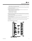
5. Install a jumper across the P and P1 terminals (remote setpoint input), and another jumper
across terminals 6 and 7 (reset input) if reset is enabled.
6. Disconnect the wires from terminals T and T1 (discharge air sensor).
7. Remove the 3,400 ohm resistor (blue leads) from the test kit and connect it across terminals T
and T1 to simulate a discharge air temperature of 60ºF.
8. Set the “Setpoint F” dial at 56ºF or below; then set the “Control Band F” dial at 2 to minimize
the control response time.
9. At the Discharge Air controller, verify that the controller ground wire is connected to the chassis
ground. Refer to the unit wiring diagram that shipped on the unit.
Note: It is not necessary to set the “Reset F” dial since the factory installed jumper across
Terminals 6 and 7 disables this dial.
10. Turn the control circuit switch 1S2, in the unit control panel, and the main power disconnect
switch for the condensing unit to the “ON” position.
ƽ WARNING
High Voltage is Present at Terminal Block 1TB1 or Unit Disconnect
Switch 1S1.
To prevent injury or death form electrocution, it is the responsibility of the technician to
recognize this hazard and use extreme care when performing service procedures with the
electrical power energized.i
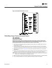
After approximately 2 minutes (time required to drive the economizer fully open), the LEDs on the
W7100 should begin to illuminate as the cooling outputs stage “On”.
11. At the Discharge Air Controller, use a digital voltmeter to verify there is 24 volts AC across
terminals TR & TR.
12. Set the “Setpoint F” dial at 64ºF; within 10 seconds, the LEDs should turn “Off” as the cooling
outputs stage “Off”.
13. Immediately readjust the “Setpoint F” dial to 56oF; the LEDs should begin to illuminate again
as the cooling outputs stage “On”.
If the unit includes the zone reset option, proceed to the next step; if not, proceed to step 18.
14. Set the “Reset F” dial at 15oF and the “Setpoint F” dial at 41ºF; then remove the jumper across
terminals 6 & 7.
To simulate a call for maximum reset, install the 1780 ohm resistor (red leads), from the test kit,
across terminals 6 and 7. The cooling LEDs should remain lit.
15. Turn the “Setpoint F” dial to 49ºF; within 1 to 2 minutes, the LEDs should turn “Off” as the
cooling outputs stage “Off”.
16. As soon as all of the cooling LEDs are “Off”, remove the 1780 ohm resistor from terminals 6 and
7 and re-install the jumper across these terminals.
17. Adjust the “Setpoint F” dial to 56ºF; within 1 minute, the LEDs should illuminate as the cooling
outputs stage “On”.
If the system includes an economizer, complete steps 18 through 23 to verify proper economizer
control operation; if not, proceed to step 24.
18. With all of the cooling LEDs “On”, measure the DC voltage across terminals R (-) and W (+). The
measured voltage should be 1.7 VDC to 2.1 VDC.
19. Set the “Setpoint F” dial at 64ºF to drive the economizer output to the minimum position.
Within 2 minutes, the LEDs should turn “Off” as the cooling outputs stage “Off”.