


68 SS-SVX09A-EN
System Pre-Start Procedures
Use the checklist provided below in conjunction with the “General Unit Requirement” checklist” to
ensure that the unit is properly installed and ready for operation. Be sure to complete all of the
procedures described in this section before starting the unit for the first time.
ƽ WARNING
Hazardous Voltage!
Disconnect all electric power, including remote disconnects before servicing. Follow proper
lockout/tagout procedures to ensure the power can not be inadvertently energized. Failure to
disconnect power before servicing could result in death or serious injury.
[ ] Turn the field supplied disconnect switch, located upstream of the unit, to the “Off” position.
[ ] Turn the “System” selection switch (at the Remote Panel) to the “Off” position and the “Fan”
selection switch (if applicable) to the “Auto” or “Off” position.
[ ] Check all electrical connections for tightness and “point of termination” accuracy.
[ ] Verify that the condenser airflow will be unobstructed.
[ ] Check the condenser fan blades. Ensure they rotate freely within the fan orifices and are securely
fastened to the fan motor shaft.
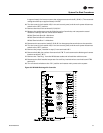
[ ] Disable the compressor (s) by unplugging the reset relay for each circuit. Refer to the unit-wiring
diagram that sipped with the unit.
NOTICE
Compressor Damage!
Do not allow liquid refrigerant to enter the suction line. Excessive liquid accumulation in the
liquid lines could result in compressor damage.
[ ] Verify that all compressor service valves, discharge service valves, and liquid line service valves
is back seated on each circuit.
COMPRESSOR SERVICE VALVES MUST BE FULLY OPENED BEFORE START-UP
(SUCTION, DISCHARGE, LIQUID LINE, AND OIL LINE).
[ ] Remove the protective plastic coverings that shipped over the compressors.
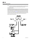
[ ] Check the compressor oil levels. The oil level in each manifold set of compressor sight glasses
should be equally 1/2 to 3/4 full when they are “Off”.
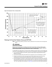
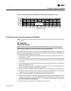
[ ] Pack Stock Units;
Two low pressure switches are installed at the factory. However, only one is wired into the control
circuit. This is to facilitate either an EVP chiller application or an air over evaporator application.
Before starting the system, verify that the correct pressure switch for the application is connected
to the control circuit. Refer to Table 13 for the pressure control settings and the unit wiring diagram,
that shipped with the unit, for the appropriate connections.
[ ] Check the condenser coils. They should be clean and the fins should be straight. Straighten any
bent coil fins with an appropriate sized fin comb.
[ ] Inspect the interior of the unit for tools and debris.
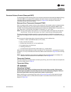
EVP Chiller Applications
[ ] Fill the chilled water system.
[ ] Vent the chilled water system at the highest points in the system. Brazed plate heat exchangers
should be purged with water through the field provided vent ports to displace any air in the heat
exchanger. Shell and tube heat exchanges (chiller barrels) should have the vent plug removed