


50 SS-SVX09A-EN
Installation
liquid line solenoid valve(s).
Supply Fan Interlock
(Control options utilizing an Air Handler)
The normally open evaporator fan interlock auxiliary contacts and the evaporator fan controls;
system On/Off switch, fan starter/contactor, and overloads, must be wired as illustrated in the
appropriate interlock connection wiring diagram for the specified application.
EVP Interlocks
(EVP Flow control 6S58)
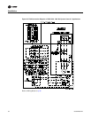
The flow switch is a binary output device and must be wired within the interlock circuit. Before
installing the control wiring, refer to the remote panel illustration for the electrical access into the
panel. Refer to the field connection diagram for the specific connection points inside the remote
panel.
ƽ WARNING
Ground Wire!
All field-installed wiring must be completed by qualified personnel. All field-installed wiring
must comply with NEC and applicable local codes. Failure to follow this instruction could result
in death or serious injuries.
ƽ WARNING
Grounding Required!
Follow proper local and state electrical code on requirements for grounding. Failure to follow
code could result in death or serious injury.
Provide a proper ground for all control circuitry at the ground connection screws provided within
both the remote panel and the unit’s control panel.
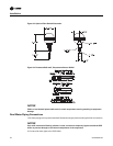
(EVP Circulating Pump Interlock)
Pump operation and sequence is the responsibility of the installer. During compressor operation,
the fluid flow through the chiller must be maintained. The field provided; ON/OFF switch, pump
starter/contactor, auxiliary contacts and overloads (OL’s) must be installed as part of the system’s
interlock circuit to disable the compressors in the event the circulating pump shuts down or is
turned off.
Note: Due to the location of the 5S1 switch within the circulating pump control circuit, it can be
used as a system ON/OFF switch.
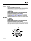
(Outside Air Thermostat 5S57)
A field provided outside air thermostat must be installed within the interlock circuit to prevent the
system from operating below it’s workable temperature range. Before installing the control wiring,
refer to the remote panel illustration for the electrical access into the panel. Refer to the field
connection diagram for the specific connection points inside the remote panel. Refer to the “EVP
Chiller Controls” section for temperature requirements.
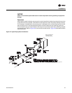
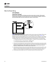
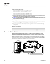
Hot Gas Bypass
(All control options)
If hot gas bypass is required, refer to the “Refrigerant Piping” illustration for supporting equipment
tubing connections. Refer to the specific control option field connection diagram terminal
connections for the hot gas bypass solenoid coils.