


SS-SVX09A-EN 73
System Pre-Start Procedures
In approximately 5 minutes; measure the voltage across terminals R (-) & W (+). The measured
voltage should drop to approximately 0.2 VDC.
20. Turn the control circuit switch 1S2, in the unit control panel, and the main power disconnect
switch to the “OFF” position.
21. Remove the wires from terminals R, B, W, & Y.
22. Measure the resistance across the following pairs of terminals, and compare the actual
resistance readings with the values shown below.
W7100 Terminals R-to-W = 226 ohms
W7100 Terminals R-to-B = 432 ohms
W7100 Terminals R-to-Y = 226 ohms
23. Reconnect the economizer leads R, B, W, & Y to the appropriate terminals on the controller.
24. Turn the control circuit switch 1S2, in the unit control panel, and the main power disconnect
switch to the “OFF” position.
25. Remove the jumper, installed in step 5, from terminals 6 & 7.
26. Remove the 3,400 ohm resistor from terminals T & T1 and reconnect the discharge air sensor
leads to terminals T & T1.
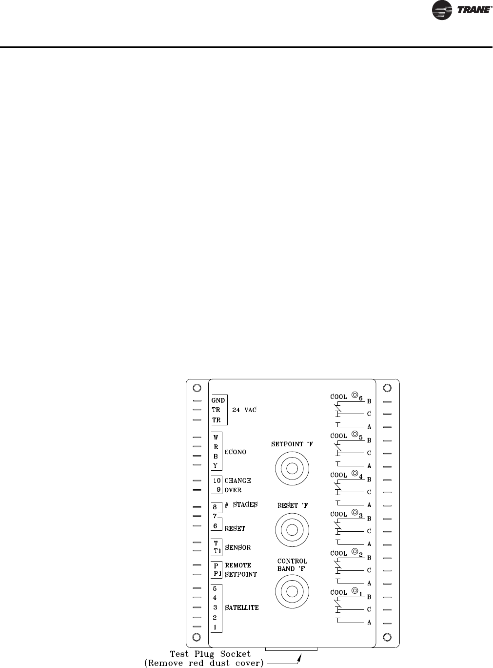
27. Remove the “Test Plug” from the W7100 test socket and reinstall the red dust cover.
28. Reconnect the field installed evaporator fan auxiliary interlock wire to terminal board 7TB5
terminal 3.
29. Turn all control switches to the “On” position and restore main power to the system.
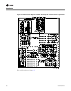
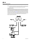
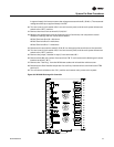
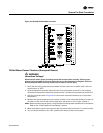
Figure 36. W7100A Discharge Air Controller