


SS-SVX09A-EN 49
Installation
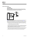
Field Installed Control Wiring
ƽ WARNING
Hazardous Voltage!
Disconnect all electric power, including remote disconnects before servicing. Follow proper
lockout/tagout procedures to ensure the power can not be inadvertently energized. Failure to
disconnect power before servicing could result in death or serious injury.
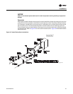
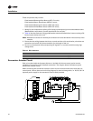
Before installing any connecting wiring, refer to Figure 3 to Figure 8 for the electrical access
locations provided on the unit. Install appropriately sized control wiring for the 115 volt electrical
components as required by the application.
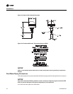
Since the unit-mounted 115V control power transformer (1T1) is provided on all units, it is not
necessary to run a separate 115 volt control power source to the unit.
Note: 200/230 Volt units are shipped with transformer 1T1 wired for 200 volt operation. If the unit
is to be operated on a 230 volt power supply, rewire the transformer as shown on the unit
schematic.
Controls Using 115 VAC
ƽ WARNING
Hazardous Voltage!
Disconnect all electric power, including remote disconnects before servicing. Follow proper
lockout/tagout procedures to ensure the power can not be inadvertently energized. Failure to
disconnect power before servicing could result in death or serious injury.
Install appropriately sized 115 volt control wiring for the electrical components as required by the
application.
These components may include:
hot gas bypass solenoid wiring;
supply fan interlock and control circuit;
system control switch wiring (“No Control” units);
step controller wiring (“No Control” units);
chilled water pump interlock wiring (EVP units);
chilled water flow switch wiring (EVP units);
outside air thermostat wiring (EVP units):
RAUC-C609
380/415/50/
3XL
342-418/
373-456
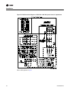
122 125 125 0.75 6 1.0 1.7 9.2 4 _ 26.2 _ 174.0 _ 16.4
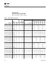
1. Electrical data is for each individual motor.
2. Max Overcurrent Protection device permitted by N.E.C. 440-22 (1993) is 225% of the largest compressor motor RLA plus the remaining motor RLA
and FLA values.
3. Minimum circuit ampacity is 125% of the largest compressor motor RLA plus the remaining motor RLA and FLA values.
4. Recommended dual element fuse size is 150% of the largest compressor motor RLA plus the remaining motor RLA and FLA values.
5. Kw values are taken at conditions of 45ºF saturated suction temperature at the compressor and 95ºF ambient.
6. Local codes may take precedence.
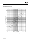
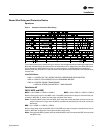
Table 8. Electrical Service Sizing Data (continued)
Model
Electrical
Charac.
Unit Characteristics Condenser Fan Motor Compressor Motor
Allow-
able
Voltage
Range
Min.
Circuit
Amp
Max.
Over-
current
Protect
-ion
Rec.
Dual
Element
Fuse
Size No
RLA
(Ea)
10
Ton
RLA
(Ea)
15
Ton
LRA
(Ea)
10
Ton
LRA
(Ea)
15
Ton
Kw
(Ea)
10
Ton
Kw
(Ea)
15
Ton
KW
(Ea) No HP
FLA
(Ea)
LRA
(Ea)