


78 SS-SVX09A-EN
System Pre-Start Procedures
Master Energy Control Checkout
ƽ WARNING
Hazardous Voltage!
Disconnect all electric power, including remote disconnects before servicing. Follow proper
lockout/tagout procedures to ensure the power can not be inadvertently energized. Failure to
disconnect power before servicing could result in death or serious injury.
1. Open the system control switches 5S1 and 5S2 to disable the Evaporator Fan and Heating
system.
2. Verify that the main power disconnect switch and the control circuit switch 1S2, in the unit
control panel, is “OFF”.
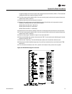
3. At the Master Energy Controller (7U11), in the unit control panel, remove at least one wire from
each of the “Heat Relay” normally open contacts and one from each of the “Cool Relay”
normally open contacts. Insulate the wires with tape to prevent shorting or grounding during
control checkout.
4. Close the main power disconnect switch and turn the control circuit switch 1S2, in the unit
control panel, “ON”.
ƽ WARNING
High Voltage is Present at Terminal Block 1TB1 or Unit Disconnect
Switch 1S1.
To prevent injury or death form electrocution, it is the responsibility of the technician to
recognize this hazard and use extreme care when performing service procedures with the
electrical power energized.
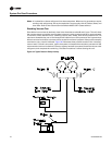
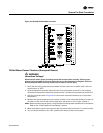
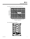
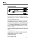
5. At the Master Energy Controller, use a digital voltmeter to verify that there is 20 volts DC power
between terminals 1 (N) & 2 (+20). Refer to the illustration in Figure 36 for terminal
identification.
Note: The wires that are still connected to one side of the “Cool Relay” contacts, are active with
115 volts applied. Ohming the contacts when only one wire is connected will not cause any
damage to the ohmmeter. However, do not try to ohm any set of contacts with wires
connected to both terminals of that contact.
6. To verify the “Heating” output relays are operating;
a. place a jumper between Terminals 2 (+20) & 5 (H).
b. place the ohmmeter leads across each set of normally open “Heat Relay” contacts. The
ohmmeter should read “Resistance” which indicates that the heating output relays have
“pulled in”.
7. To verify the “Cooling” output relays are operating;
a. Remove the jumper from Terminals 2 (+20) & 5 (H) and reinstall it between Terminals 2 (+20)
& 4 (C).
b. place the ohmmeter leads across each set of normally open “Cool Relay” contacts. The
ohmmeter should read “Resistance” which indicates that the cooling output relays have
“pulled in”.
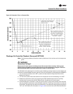
8. With all of the “Cooling Output” relays pulled in (step 7), measure the DC voltage across
Terminals R (-) and W (+). The measured voltage should be approximately 1.7 to 2.1 VDC.
9. Remove the jumper installed between Terminals 2 (+20) & 4 (C).