


56 SS-SVX09A-EN
Installation
Variable Air Volume Control (Honeywell W7100A)
In a variable air volume system, the desired space temperature is maintained by varying the
amount of conditioned air being delivered to the space. As the cooling requirements of the space
decreases, less air is delivered to the zone; conversely, as the cooling requirements of the space
increases, a greater volume of air is delivered to the zone.
The descriptions of the following basic input devices used with the Honeywell W7100A discharge
air controller are to acquaint the operator with their function as they interface with the controller.
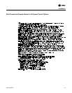
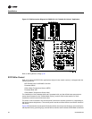
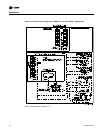
Refer to the field connection diagram in Figure 27 for the specific component connections at the
unit control panel.
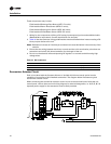
For discussion of evaporator fan interlock, hot gas bypass, and economizer connections, refer to
the “Controls Using 115 VAC” section. Refer to Figure 26 for the specific component connections.
Discharge Air Sensor (Honeywell 6RT3)
Each unit ordered with variable air volume controls (digit 9 in the model number) is shipped with
a Honeywell 6RT3 discharge air sensor.
ƽ WARNING
Hazardous Voltage!
Disconnect all electric power, including remote disconnects before servicing. Follow proper
lockout/tagout procedures to ensure the power can not be inadvertently energized. Failure to
disconnect power before servicing could result in death or serious injury.
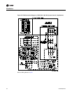
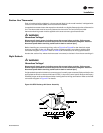
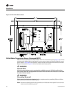
The sensor should be installed in a turbulent free area of the discharge air duct at a location that
will provide accurate supply air sensing. Refer to the illustration in Figure 26 for installation and
sensor dimensional information.
The sensor serves two functions;
1. It sends the supply air temperature data to the Discharge Air Controller, in the form of an analog
input, to control the economizer (if applicable) and the cycling of the compressors.
2. It serves as a low limit sensor for the system when the supply air temperature reaches too high
a delta tee between the actual supply air temperature and the supply air temperature setpoint.
Before installing any connecting wiring, refer to Figure 3 to Figure 8 for the electrical access
locations provided on the unit. Wire the sensor in accordance with the field connection diagram
in Figure 27. Shielded cable (Belden 8760 or equivalent) must be used when wiring the sensor to
the terminal board inside the unit’s control panel.
Connect the shielded cable to the appropriate terminals on the terminal board (7TB7), in the unit’s
control panel.
ƽ WARNING
Ground Wire!
All field-installed wiring must be completed by qualified personnel. All field-installed wiring
must comply with NEC and applicable local codes. Failure to follow this instruction could result
in death or serious injuries.
ƽ WARNING
Grounding Required!
Follow proper local and state electrical code on requirements for grounding. Failure to follow
code could result in death or serious injury.
Ground the shield (at the unit only) using the ground screw in the “customer 24 volt connection
area as shown in the field connection diagram.