


SS-SVX09A-EN 87
System Start-Up
Low Ambient Thermostats
In addition to the low ambient dampers on 25, 30, 50 & 60 Ton units, a low ambient thermostat is
installed to further restrict the airflow across the condenser by cycling the 2B3 condenser fan on
25 & 30 Ton units plus 2B6 on 50 & 60 Ton units. The thermostat opens when the ambient
temperature reaches 30ºF and closes at approximately 33ºF.
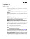
Hot Gas Bypass Operation
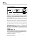
The HGBP valve regulates evaporator pressure by opening as suction pressure decreases, to
maintain a desired minimum evaporating pressure regardless of a decrease in evaporator external
loading.
When the evaporator (suction) pressure is above the valve’s setpoint, it remains closed. As suction
pressure falls below the valve’s setpoint, the valve begins to open. The valve will continue to open
at a rate proportional to the suction pressure drop, thus maintaining evaporator pressure.
Hot gas bypass valves are adjustable and should be set to begin opening at approximately 58 psig
suction pressure and reach the full open position at 51 psig for DX coil applications. For EVP chiller
applications, the regulator should be adjusted to begin opening at approximately 69 psig suction
pressure and reach full open position at 61 psig.
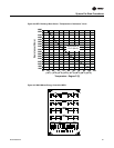
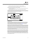
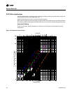
Low Ambient Damper Adjustment (Factory or Field Installed)
When a unit is ordered with the low ambient option (i.e., Digit 11 is a “1” in the model number),
a damper is factory installed over the lead condenser fan for each refrigeration circuit. Refer to the
appropriate unit illustrated in Figure 43 for the damper locations.
For field installation, mount the dampers over the condenser fans at the locations shown in
Figure 43 and connect the actuator, controller, and sensor for each circuit. (Refer to the Installation
Instructions provided with each low ambient damper kit.)
The controller has a factory default setpoint of 105 F. This setpoint can be adjusted by installing a
field supplied resistor on 2TB34 in the low ambient control panel located in the back of the main
control panel. (See the low ambient wiring diagram, that shipped with the unit or with the field kit,
for resistance values and installation location.)
ƽ WARNING
Live Electrical Components!
During installation, testing, servicing and troubleshooting of this product, it may be necessary
to work with live electrical components. Have a qualified licensed electrician or other individual
who has been properly trained in handling live electrical components perform these tasks.
Failure to follow all electrical safety precautions when exposed to live electrical components
could result in death or serious injury.
Inspect the damper blades for proper alignment and operation. Dampers should be in the closed
position during the “Off” cycle. If adjustment is required;
1. Remove the sensor leads from the input terminals 6 and 7 for circuit #1 and/or 11 and 12 for
circuit #2. (Controller output signal will go to 0.0 VDC and the damper will drive to the closed
position.)
2. Loosen the damper shaft “Locking” set screws on the actuator
3. Firmly hold the damper blades in the closed position
4. Retighten the “Locking” set screws.
To check damper operation, jumper between the sensor input terminals 6 and 7 and/or 11 and 12
(if applicable). Controller output signal will go to 10 VDC and the damper will drive to the full open
position.