


Terminal Unit
Control (TUC)
90 UNT-IOM-6
3. Rotate the setpoint dial on the zone sensor module to 55° F for
cooling or 85° F for heating.
The appropriate control valve will actuate assuming the following
conditions:
· Room temperature should be greater than 55° F and less
than 85° F
· For a 2-pipe fan-coil unit with an automatic changeover
sensor, the water temperature input is appropriate for the
demand placed on the unit, e.g. cooling operation is re-
quested and cold water (5° F lower than room temperature
for a TUC) flows into the unit.
4. Select the correct temperature setpoint.
Note: Select and enable zone sensor temperature settings to prevent
freeze damage to unit.
TUCs connected to a Tracer
®
comm 4 communication link requires a
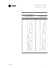
unique address. Use the TUCs eight DIP switches to set the ICS
address. The address must be in the valid range of 33 to 96. See
Table 21 on page 63 for address settings.
To set the ICS address, perform the following steps:
1. Set the DIP switches to the correct address. ON implies that the
DIP switch is pressed towards the DIP switch number. OFF implies
that the DIP switch is pressed towards the OPEN position.
2. Short and hold the test input (J11 and J12) until all LEDs are
illuminated. Remove the jumper from the test input. This sets the
address in the TUC EEPROM.
Note: Cycling power to the TUC forces the TUC to read the DIP
switch settings (Rev 12 TUC or higher). The TUC firmware version
can be read from either Tracer or Everyware. Additionally, the last two
digits of the part number printed on the sticker on the TUC 1U1
microprocessor indicate the TUC firmware version, ie: 6200-0028-
13.
The TUC operates the fan in the following modes:
Setting the ICS Ad-
dress for Tracer Com-
munications
TUC Human
Interface