


Tracer
®
ZN.520
60 UNT-IOM-6
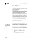
Follow these general guidelines when installing communication
wiring:
1) Maintain a maximum 5000 ft. aggregate run
2) Install all communication wiring in accordance with the NEC
and all local codes.
3) Solder the conductors and insulate (tape) the joint sufficiently
when splicing communication wire. Do not use wire nuts to
make the splice.
4) Do not pass communication wiring between buildings be
cause the unit will assume different ground potentials.
5) Do not run power in the same conduit or wire bundle with
communication link wiring.
Establish service communication using Rover service software
connected to the Tracer
®
ZN.520 using a twisted wire pair to one of
the following connection points.
1) Remote zone sensor module
2) Connections on the board
This allows the technician to view and edit the Tracer
®
ZN.520
configuration and troubleshoot the unit. However, control options
ordered and the wiring practice followed in the field may limit the
communication ability.
Route interconnecting wiring from the Tracer
®
ZN.520 to provide
service communication at the wall-mounted zone sensor module.
Install wiring by referencing the unit wiring diagram and Table 3 on
page 35 for appropriate wire sizes. After wiring is complete, connect
the communication cable (provided with the Rover service tool) to the
telephone style RJ11 connection on the zone sensor module. Attach
the other end of the cable to a laptop computer running Trane Rover
software to establish communication.
Establish service communication to the Tracer
®
ZN.520 by wiring
directly to the board inside the control box. Reference the unit-wiring
diagram for the appropriate communication terminals on the board.
Once wiring is complete, Use Trane Rover software to communicate
to the Tracer
®
ZN.520.
Service
Communication
Wiring
Wall Mounted Zone
Sensor Module
Zone Sensors Without
Interconnecting Wiring