


22 UNT-IOM-6
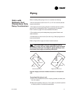
Note: For vertical fan-coil units, push the main condensate drain
hose and overflow condensate drain hose through to the inside of the
chassis end panel to prevent them from being burned when making
sweat connections. Be sure to pull the hoses back through and route
to the auxiliary drain pan when the end panel has cooled.
3. Solder the joint using bridgit lead-free solder (ASTM B32-89) to
provide a watertight connection. Avoid overheating factory soldered
joints when soldering field connections to the coil to prevent
leakage from occurring.
4. Insulate all piping to coil connections as necessary after connec-
tions are complete.
Note: Maintain a minimum distance of one foot between the reduction
fitting for the 1/2 inch diameter line and the fan-coil unit piping
connections.
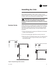
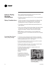
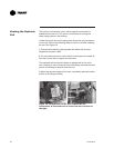
Install the auxiliary drain pan, which ships in the accessory packet
CAUTION: In all steam coil installations, the con-
densate return connections must be at the low point of
the coil to ensure condensate flows freely from the coil
at all times. Failure to do so may cause physical coil
damage from water hammer, unequal thermal stresses,
freeze-up and/or corrosion.
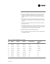
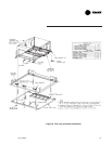
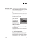
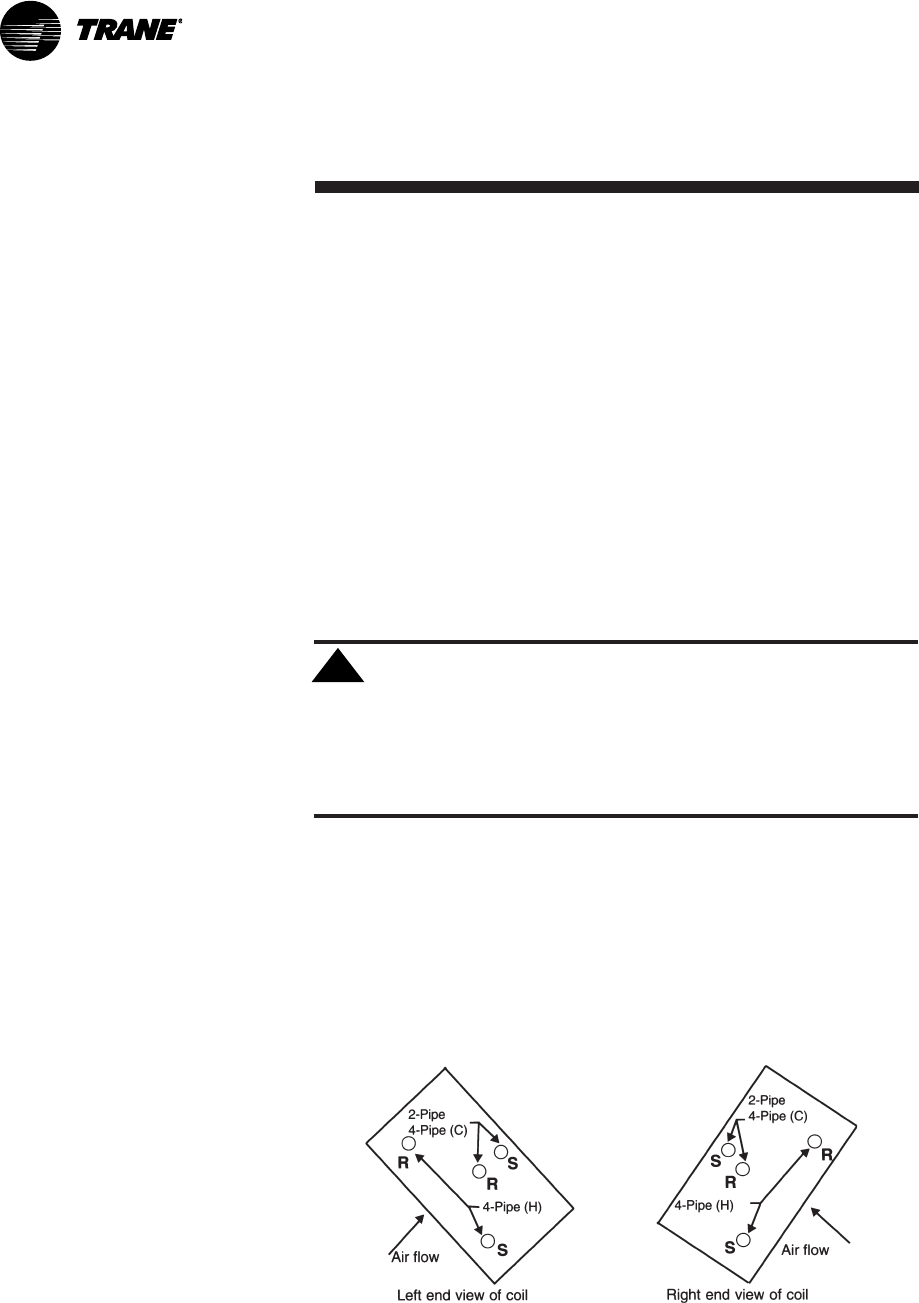
1. Make piping connections to the steam coil as shown in Figure 7.
Cap the unused connection.
2. The coil is already pitched within the unit to provide proper pitch to
drain condensate out of the coil. Ensure that the unit has been
properly leveled. Refer to page 13 for unit leveling instructions.
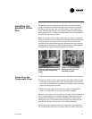
3. Install a 1/2 inch, 15-degree swing check vacuum breaker in the
unused condensate return tapping as close as possible to the coil.
Units with Steam
Coils
!
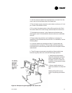
Figure 7. Steam coil header ports. The center port is the supply
connection. The return port is below the supply. The top port
must be closed off.