


UNT-IOM-6 47
Tracer
®
ZN.010
and ZN.510
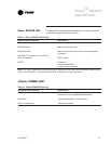
Table 12. Yellow COMM LED Activity
Yellow LED Blink Activity Description
LED off continuously The controller is not detecting any communication.
(Normal for units in standalone applications)
LED blinks The controller detects communication.
LED on continuously Abnormal condition
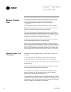
Table 11. Green STATUS LED Activity
Green LED Blink Activity Description
LED on continuously Power on (normal operation)
LED blinks once Manual output test mode
LED blinks twice Manual output test mode, with one or more diagnos-
tic present
LED blinks (1/4 second on, 1/4 second
off for 10 seconds) Wink mode
LED off · Power off
· Abnormal condition
· Test button is pressed
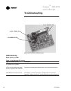
Green STATUS LED
Note: The wink feature allows the identification of a particular controller. When sending a request from a
device, such as Rover, the controller will wink to indicate it received the signal.
Yellow COMM LED
The green LED normally indicates whether the controller is powered
on (24 VAC supplied). Reference Table 11.