


UNT-IOM-6 33
Electrical Connections
Supply Power
Wiring
Refer to the unit nameplate to obtain the minimum circuit ampacity
(MCA) and maximum fuse size (MFS) or maximum circuit breaker
(MCB) to properly size field supply wiring and fuses or circuit break-
ers. See Figure 2 on page 6 to reference the nameplate location.
Refer to the unit operating voltage listed on the unit wiring schematic,
submittal, or nameplate. Reference the wiring schematic for specific
wiring connections.
WARNING: Hazardous voltage! Disconnect all
electric power including remote disconnects before
servicing. Failure to do so may cause severe personal
injury or death.
Wiring diagrams are attached to the unit in a plastic bag and can be
be easily removed for reference. Wiring schematics are attached as
follows:
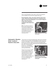
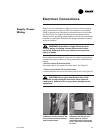
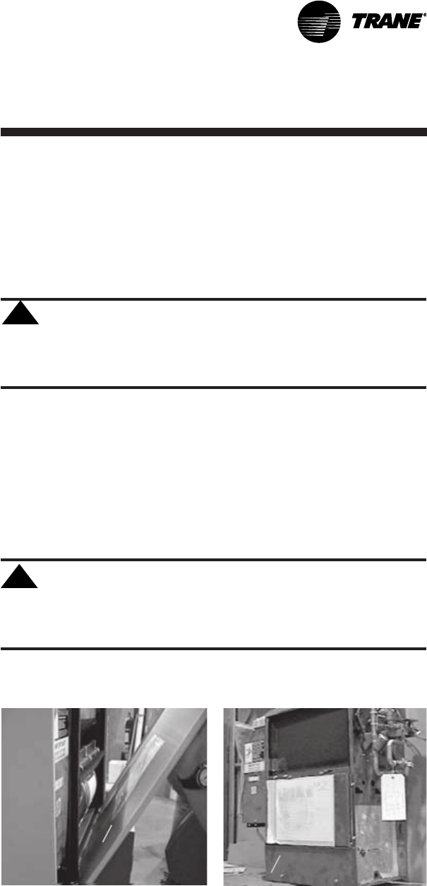
· Vertical cabinet & recessed units:
Schematics are on the inside of the front panel. See Figure 21.
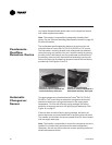
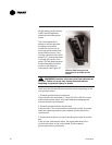
· Vertical concealed & all horizontal units:
Locate schematics on the fan and motor panel of unit. See Figure 22.
CAUTION: Use copper conductors only! Unit
terminals are not designed to accept other types of
conductors. Failure to do so may cause damage to the
equipment.
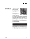
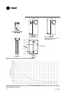
Figure 22. Locate the wiring
schematic on the fan and
motor panel of vertical
concealed and all horizontal
units. (This unit is turned on
it's side.)
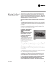
Figure 21. Locate the wiring
schematic on the inside of the
front panel of vertical cabinet
and recessed units.
!
!