


Terminal Unit
Control (TUC)
114 UNT-IOM-6
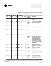
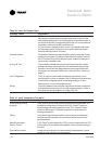
Table 50. Fresh Air Damper Open
Probable Cause Explanation
Normal Operation · The two-position fresh air damper opens under normal unit opera
tion during occupied mode and closes during unoccupied mode.
· Modulating analog and 3-wire floating point economizers open to
the minimum position (configurable) when the unit is occupied and
modulate to meet unit capacity requirements.
· If the minimum damper position is zero, the damper may close
for extended periods. During the unoccupied mode, the normal
fresh air damper position is closed.
Override Present The fresh air damper may be overridden open by either the Tracer
®
system or Everyware software. Whenever any override is active,
the TUC drives the fresh air damper closed, unless the damper is
concurrently overridden open.
Autocycle Test The controller includes an autocycle test sequence that verifies
analog and binary output operation and associated output wiring.
However, the current test stage sequence may require the fresh
air damper may be open. Refer to the Autocycle Test section on
page 71.
Unit Configuration The TUC cannot control fresh air damper outputs if the unit is
configured for no fresh air damper. Also, if the fresh air damper type
is incorrectly configured (on/off, modulating analog, or 3-wire
floating point), it may not operate properly.
Wiring The wiring between the controller outputs and the fresh air damper
must be present and correct for normal damper operation. Refer to
the typical unit wiring diagrams on pages 105-106.
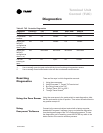
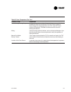
Table 51. Zone Temperature Too Warm
Probable Cause Explanation
Active heating/cooling Verify that the active heating/cooling setpoints are reasonable. It is
setpoints possible for either the zone sensor or for the Tracer
®
system to
send heating and cooling setpoints to the TUC. Use the Tracer
®
system or Everyware software to determine which source is
sending the setpoint.
Wiring Verify the wiring of all end devices, such as valves and dampers.
Use the manual overrides or the autocycle test to verify the end
device operation.
Manual heat mode If the Tracer
®
system places the TUC in manual heat mode, the TUC
sent by Tracer
®
cannot switch to cool mode and therefore cannot provide cooling to
the zone.
Zone sensor location Locate the zone sensor in an area where the temperature is repre-
sentative of the average zone temperature.