


UNT-IOM-6 15
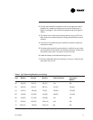
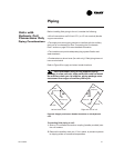
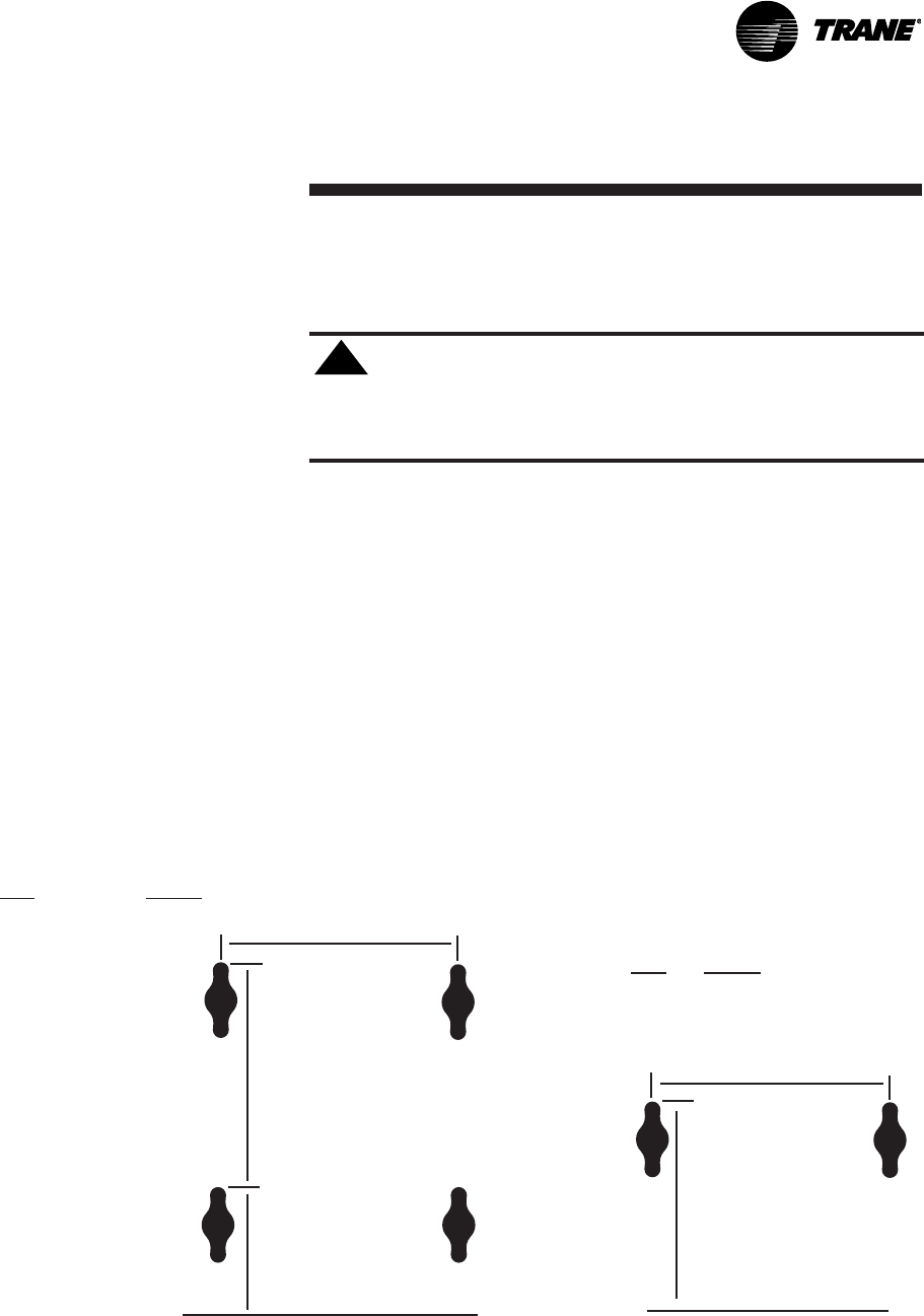
Size L (in.)
02 21 1/4
03 21 1/4
04 26 1/4
06 35 3/4
08 44 1/4
10 63 1/4
12 63 1/4
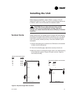
Floor Level
15.5 in.
7.5 in.
L
L
12.19 in.
Floor Level
Vertical Units
Figure 4. Keyslot Hanger Hole Locations
Installing the Unit
Before beginning installation, refer to Table 1 on page 17 for unit
weights and Figure 3 on page 12 for service and operating clearances.
In addition, refer to the unit submittal for installation details.
CAUTION: Do not allow electrical wire to fall
between the unit and installation surface. Failure to
comply may cause electrical shorts or difficulty in access-
ing wires.
Install vertical units in an upright position using the 5/8 inch diameter
double key slot hanger holes, located on the back of unit. The hanger
holes allow a maximum shank size of 5/16 inch diameter threaded
rods or lag screws (installer provides). Follow the installation proce-
dure below.
1. Prepare wall openings for recessed units. Reference unit submittal
for each unit size dimensions.
2. If the unit has leveling legs, adjust them correctly to level unit.
3. Mark the position of the keyslot hanger holes on the wall according
to the dimensions given in Figure 4 for each unit size. Align the
hole locations evenly.
!
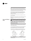
Cabinet & Concealed Units
Size L (in.)
03 26 1/4
04 35 3/4
06 44 1/4
Low Vertical Cabinet & Concealed