


UNT-IOM-6 109
Terminal Unit
Control (TUC)
More detailed information about programming and operating the TUC
board can be found in Trane publication, EMTX-IOP-1 TUC Installa-
tion Operation and Programming Guide.
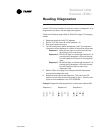
Troubleshooting
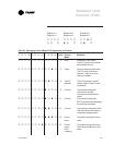
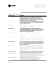
Table 44. TUC Does Not Communicate
Probable Cause Explanation
TUC is not addressed correctly Verify the ICS address according to Table 21 on page 63. Each TUC
on the link requires a unique address in the range of 33 to 96. Set or
modify the DIP switches, then short the TUC test input momentarily.
Incorrect comm 4 wiring Verify that the link is twisted pair Trane part # 400-20-28 or equiva-
lent. TUC (comm 4) wiring is polarity sensitive throughout the com-
munication link. If possible, isolate the TUC from the rest of the ICS
link to determine if the problem exists in the comm wiring or in the
TUC board.
Defective TUC board If the previous solutions do not fix the problem, it may be necessary
to replace the TUC board.
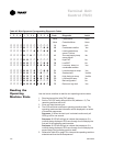
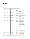
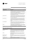
Table 45. Fan Outputs not Energizing
Probable Cause Explanation
Random start enabled When enabled, the random start feature delays the unit start-up for
3 to 32 seconds (configurable) after power-up.
Power-up control wait When enabled, the power-up control wait feature delays the TUC
startup for two minutes after power-up. This delay allows the
Tracer
®
system ample time to communicate its fan control request.
Cycling fan operation When configured to cycle with capacity, the unit fan cycles off when
there is no call for heating or cooling. The heating/cooling sources
cycle on or off periodically with the unit fan to match the capacity
according to pulse-width-modulation (PWM) logic.
Unoccupied operation The fan cycles with capacity when the unit is in unoccupied mode.
This occurs even if the unit is configured for continuous fan opera-
tion. While unoccupied, the fan cycles on or off with heating/
cooling to match the capacity according to pulse-width-modulation
(PWM) logic. The TUC can be placed in unoccupied mode either
through a Tracer
®
system or through BIP3 if it has been configured
as occupied/unoccupied.
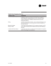
Latching diagnostic present A specific list of diagnostics effects fan operation. For more informa-
tion, see the Diagnostics section on page 73. Latching diagnostics
require a manual reset to restore normal unit operation.
Unit disabled The Tracer
®
system can disable the unit via a shutdown input or
BIP1 can be configured as external interlock.
Local fan switch: off Using the local fan mode switch to determine fan operation, the
off position on the switch controls the unit fan to off.