


Tracer
®
ZN.010
and ZN.510
54 UNT-IOM-6
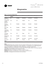
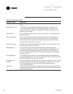
Table 16. Valves Stay Closed
Probable Cause Explanation
Normal operation The controller opens and closes the valves to meet the unit capacity require-
ments.
Requested mode: off It is possible to communicate the operating mode (such as off, heat, and
cool) to the controller. When off is communicated to the controller, the unit
controls the fan to off. The unit is not capable of heating or cooling when the
controller is in this mode.
Valve override The controller can communicate a valve override request. This request effects
the valve operation.
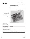
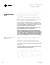
Manual output test The controller includes a manual output test sequence to verify analog and
binary output operation and the associated wiring. However, based on the
current step in the test sequence, the valves may not be open. Refer to the
Manual Output Test section on page 51.
Diagnostic present A specific list of diagnostics affects valve operation. For more information, see
the Diagnostics section on page 50.
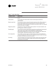
Sampling logic The controller includes entering water temperature sampling logic that
automatically invokes during 2-pipe or 4-pipe changeover. It determines when
the entering water temperature is either too cool or too hot for the desired
heating or cooling mode. Refer to the Entering Water Temperature Sampling
section on page 41.
Unit configuration The controller must be properly configured based on the actual installed end
devices and application. When the unit configuration does not match the actual
end device, the valves may not work correctly.
No power to the If the controller does not have power, the valves do not operate. For the controller
controller to operate normally, it must have an input voltage of 24 VAC. When the green
LED is off continuously, the controller does not have sufficient power,
or the controller has failed.
Unit wiring The wiring between the controller outputs and the valve(s) must be present and
correct for normal valve operation. Refer to the typical unit wiring diagrams in the
Appendix of this manual.