


UNT-IOM-6 83
Tracer
®
ZN.520
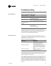
Table 32. Green Status LED activity
Green LED activity Description
On continuously Power on (normal operation)
Blinks (one blink) The controller is in manual output test mode.
No diagnostics present.
Blinks (2 blinks) The controller is in manual output test mode.
One or more diagnostics are present.
LED blinks (1/4 sec. Wink mode (Note 1).
on, 1/4 sec., off for
10 sec)
LED off Power is off.
Controller failure.
Test button is pressed.
Note 1: The Wink feature allows you to identify a controller. By
sending a request from Rover service tool, you can request the
controller to wink (blink on and off as a notification that the controller
received the signal). The green LED blinks (1/4 second on, 1/4
second off for 10 seconds) during Wink mode.
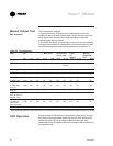
The yellow Comm LED blinks at the rate the controller receives
communication. The yellow LED does not blink when the controller is
transmitting communication data.
Table 33. Yellow Comm LED Activity
LED activity Description
Off continuously The controller is not detecting any
communication. (Normal for
standalone applications.)
LED blinks or flickers The controller detects communica
tion. (Normal for communicating
applications, including data shar
ing.)
LED on continuously Abnormal condition or extremely
high traffic on the link.
The test sequence verifies output and end device operation. Use the
manual output test to verify output wiring and actuator operation
without using Rover service tool.
If the diagnostics remain after an attempt to clear diagnostics, the
status LED indicates the diagnostic condition is still present and may
affect the manual output test.See the Green Status LED section.
Advancing completely through the test sequence terminates manual
test. The controller will time out if the unit remains in a single step for
one hour.
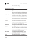
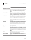
Troubleshooting
Green Status LED
Yellow Comm LED