


26 UNT-IOM-6
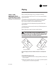
inch inside diameter flexible plastic tube over the nipple and secure
with a field supplied hose clamp.
Note: The installer is responsible for adequately insulating field
piping. See the External Insulating Requirements section on page 20
for more information.
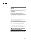
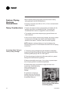
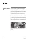
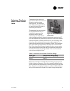
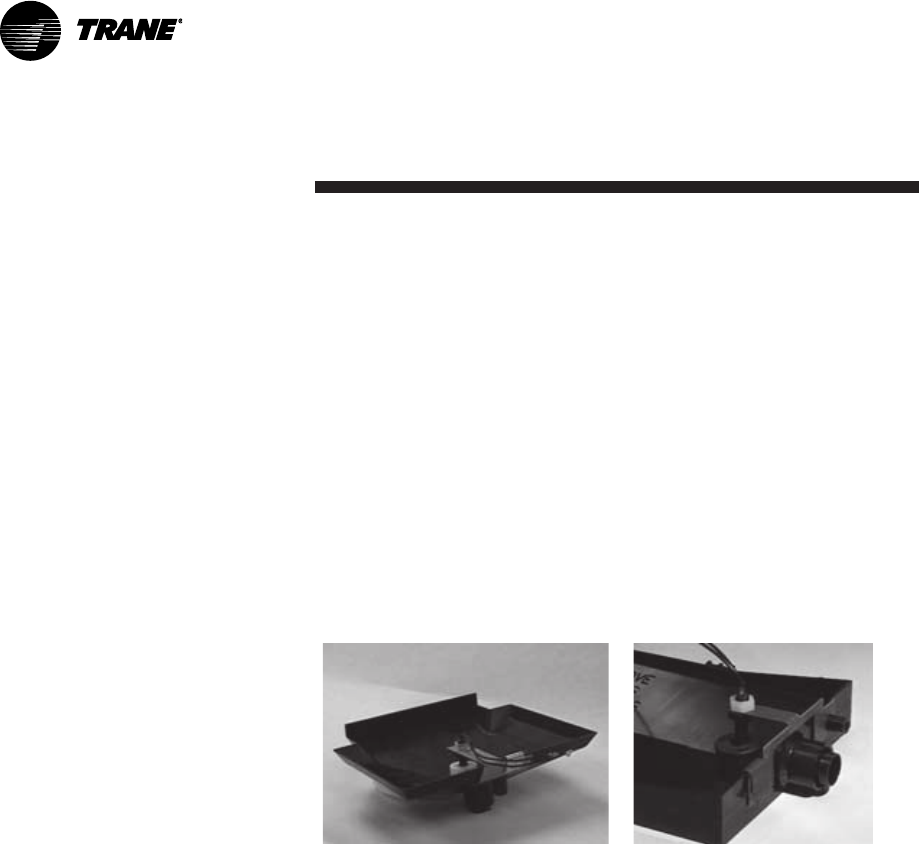
The condensate overflow detection device is an option on fan-coil
units with either a Tracer
®
ZN.010, ZN.510, ZN.520 or TUC control.
The float switch, mounting bracket, and coiled leads ship attached
inside the piping end pocket of the unit. Install the switch by placing
the hole or slot in the bracket over the condensate overflow drain (of
the auxiliary drain pan) with the switch float extending over the pan.
Secure the drain pan by attaching the pans bracket with the factory
provided clip. See Figures 12 and 13.
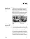
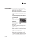
Two-pipe changeover units with either the Tracer
®
ZN.010, ZN.510,
ZN.520 or TUC control have an automatic changeover sensor that
determines heating or cooling mode based on the supply water
temperature. On units with a factory piping package, the factory
straps the changeover sensor to the piping supply water pipe. See
Figure 14 on page 27.
If the unit does not have a factory piping package, the factory at-
taches the sensor and coiled lead wires to the piping side end panel.
The installer should attach the sensor parallel to and in direct contact
with the supply water pipe.
Note: The installer is responsible to ensure the changeover sensor is
installed in a location that can sense active water temperature.
Otherwise, the unit may fail to sense the correct operating mode and
disable temperature control.
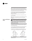
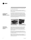
Figure 12. Condensate
overflow switch installed in a
vertical auxiliary drain pan.
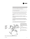
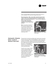
Figure 13. Condensate
overflow switch installed in a
horizontal auxiliary drain pan.
Condensate
Overflow
Detection Device
Automatic
Changeover
Sensor