


Tracer
®
ZN.520
74 UNT-IOM-6
Binary outputs are configured to support the following:
Three fan stages (when one or two fan stages are present, medium
fan speed can be configured as exhaust fan)
One hydronic cooling stage
One hydronic heating stage (dehumidification requires this to be in
the reheat position)
One DX cooling stage
One- or two-stage electric heat (dehumidification requires this to be
in the reheat position)
Face and bypass damper
Modulating outdoor air damper
One baseboard heat stage
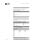
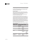
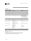
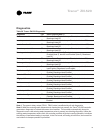
Table 27. Binary Output Configuration
Binary Output Configuration
J1-1 Fan high
J1-2 Fan medium
J1-3 Fan low
J1-4 (Key)
J1-5 Cool valve open, or 2 position valve,
(Note 1)
J1-6 Cool valve close (Note 1)
J1-9 Heat valve open, or 2 position valve, or 1
st
Electric heat stage (Note 1)
J1-10 Heat valve close or 2
nd
Electric heat stage
(Note 1)
J1-11 Fresh air damper - open
J1-12 Fresh air damper - close
TB4-1 Generic / Bbaseboard heat output
TB4-2 24VAC
Note 1: For Tracer
®
ZN.520 units configured and applied as 2-pipe
hydronic heat/cool changeover, terminals J1-5 and J1-6 are used to
control the primary valve for both heating and cooling. For Tracer
®
ZN.520 units configured and applied as 2-pipe hydronic heat/cool
changeover with electric heat, terminals J1-5 and J1-6 are used to
control the primary valve (for both cooling and heating), and terminals
J1-9 and J1-10 are used only for the electric heat stage. For those 2-
pipe changeover units, electric heat will not be energized while the
hydronic supply is hot (5 or more degrees above the space tempera-
ture).
Binary Outputs