


UNT-IOM-6 35
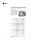
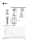
Table 3. Maximum Wiring Distances, ft (m)
Device Wire Size Range
Max. Wiring Distance
Fan Mode Switch 14 - 22 AWG
500 (152.4)
Zone Sensor Module 16 - 22 AWG
200 (60.96)
All sensor and input circuits are normally at or near ground (common)
potential. When wiring sensors and other input devices to the Tracer
®
ZN.010, ZN.510, ZN.520 or TUC, avoid creating ground loops with
grounded conductors external to the unit control circuit. Ground loops
can affect the measurement accuracy of the controller.
CAUTION: Unit transformer IT1 provides power to
fan-coil unit only. Field connections to the transformer
IT1 may create immediate or premature unit component
failure.
All input/output circuits (except isolated relay contacts and optically
isolated inputs) assume a grounded source, either a ground wire at
the supply transformer to control panel chassis, or an installer
supplied ground.
Note: Do not connect any sensor or input circuit to an external ground
connection.
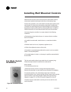
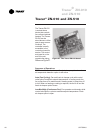
The installer must provide interconnection wiring to connect wall
mounted devices such as a fan mode switch or zone sensor module.
Refer to the unit wiring schematic for specific wiring details and point-
to-point wiring connections. Dashed lines indicate field wiring on the
unit wiring schematics. All interconnection wiring must conform to
NEC Class 2 wiring requirements and any state and local require-
ments. Refer to Table 3 for the wire size range and maximum wiring
distance for each device.
Recommendation: Do not bundle or run interconnection wiring
in parallel with or in the same conduit with any high-voltage
wires (110V or greater). Exposure of interconnection wiring to
high voltage wiring, inductive loads, or RF transmitters may
cause radio frequency interference (RFI). In addition, improper
separation may cause electrical noise problems. Therefore, use
shielded wire (Beldon 83559/83562 or equivalent) in applications
that require a high degree of noise immunity. Connect the shield
to the chassis ground and tape at the other end.
Electrical
Grounding
Restrictions
!
Wall Mounted
Control
Interconnection
Wiring