


UNT-IOM-6 27
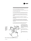
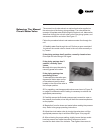
When using field supplied 3-way valves, position the changeover
sensor upstream of the valve on the supply water pipe.
Recommendation: When using field supplied 2-way control
valves, attach the changeover sensor in a location that will
detect an active water temperature. The unit must always be
able to sense the correct
system water temperature,
regardless of the control valve
position.
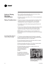
Note: The maximum length of
the automatic changeover wire
cannot exceed 10 feet from the
control panel. If the sensor
extends beyond the unit chassis,
use shielded conductors to
eliminate radio frequency
interference (RFI).
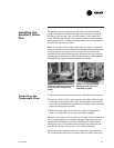
Two-pipe fan-coil units with auxiliary electric heat have an automatic
electric heat lockout switch that disengages the electric heat when
hydronic heat enables. If the unit has a factory piping package and
electric heat, the factory attaches the switch to the supply water
pipe. When the lockout switch detects the supply water temperature
above 95° F, it disengages the
electric heat. This eliminates
electric heat and hydronic heat
working simultaneously.
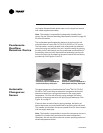
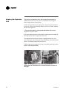
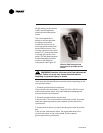
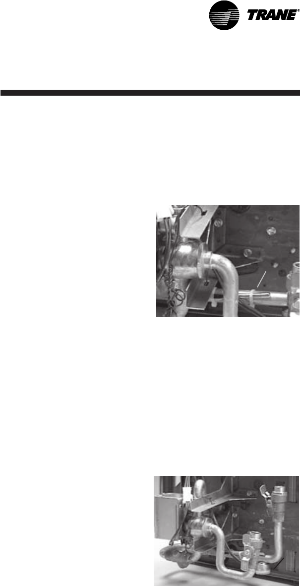
If the fan-coil unit does not have
a factory piping package, the
factory attaches the switch and
coiled lead wires to the piping
side end panel. The installer
should position the lockout
switch on the supply water line of
the unit by sliding its spring
connector over the pipe.
See Figure 15.
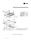
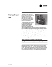
Figure 14. The changeover
sensor strapped to the supply
water pipe.
Automatic Electric
Heat Lockout
Switch (Fan-coil)
Figure 15. Units with electric
heat have an electric heat
lockout switch on the supply
water pipe.