


34 UNT-IOM-6
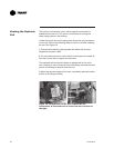
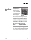
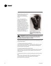
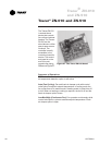
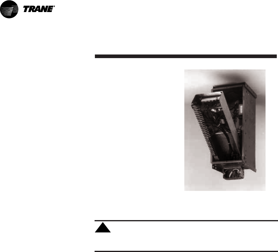
Figure 23. The terminal unit
control (TUC) board pivots
downward to provide service
access.
!
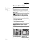
All field wiring should conform
to NEC and all applicable
state and local code require-
ments.
The control panel box is
always on the end opposite
the piping connections.
Access the control box by
removing the two screws that
secure the front cover. If the
unit has a terminal unit control
board (TUC), remove the screw
in the top right corner of the
panel. This will allow the panel
to pivot downward to provide
access to the electrical
components. See Figure 23.
WARNING: Insulate all power wire from sheetmetal
ground. Failure to do so may cause electrical shorts
resulting in personal injury or death.
Units have one of three different connection points, depending on the
unit type and options.
1. Power & ground inside of control box:
If the unit has a fan mode switch, Tracer
®
ZN.010 or ZN.510 control
without a disconnect switch, the power leads and capped ground
wire are inside the control panel.
2. Power & ground inside the junction box:
If the unit has a TUC control without a disconnect switch, the power
leads and capped ground wire are inside the junction box on the
control panel.
3. Power wired to switch on junction box & ground inside of junction
box:
If the unit has a disconnect switch, the power leads wire to the
junction box switch on the control panel. Pull the capped
ground wire into the junction box.