


130 UNT-IOM-6
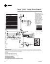
NOTES:
1. UNLESS OTHERWISE NOTED, ALL SWITCHES ARE
SHOWN AT 25 C (77 F), AT ATMOSPHERIC PRESSURE, AT
50% RELATIVE HUMIDITY, WITH ALL UTILITIES TURNED
OFF, AND AFTER A NORMAL SHUTDOWN HAS
OCCURRED.
2. DASHED LINES INDICATE RECOMMENDED FIELD WIRING
BY OTHERS. DASHED LINE ENCLOSURES AND/OR
DASHED DEVICE OUTLINES INDICATE COMPONENTS
PROVIDED BY THE FIELD. SOLID LINES INDICATE WIRING
BY TRANE CO.
3. NUMBERS ALONG THE RIGHT SIDE OF THE SCHEMATIC
DESIGNATE THE LOCATION OF CONTACTS BY LINE
NUMBER. AN UNDERLINED NUMBER INDICATES A
NORMALLY CLOSED CONTACT.
4. ALL FIELD WIRING MUST BE IN ACCORDANCE WITH THE
NATIONAL ELECTRIC CODE (NEC), STATE AND LOCAL
REQUIREMENTS.DEVICE PREFIX
LOCATION GUIDE
AREA LOCATION
1 CONTROL PANEL
2 CONTROL END
3 PIPING END
4 FAN SECTION
5 COIL SECTION
6 CUSTOMER
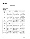
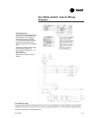
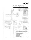
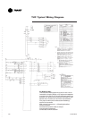
For Reference Only:
This schematic shows typical wiring of a fan-coil. It is not intended for a basis of design or for equipment installation
purposes in the field. For an as-built schematic specific to a particular unit, please see the ship-with schematic for that
specific unit or contact your local Trane representative.
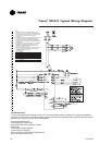
Two-pipe autochangeover
Two-position N/C control valve
Two-position N/C fresh air damper actuator
EWT sensor
Condensate overflow detection
Low temperature detection
Unit mounted fan mode switch and setpoint dial
Return air temperature sensor
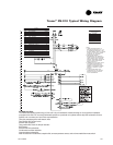
Tracer
®
ZN.010 Typical Wiring Diagram