


Terminal Unit
Control (TUC)
110 UNT-IOM-6
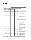
Table 45Continued. Fan Outputs not Energizing
Probable Cause Explanation
No power to the TUC The TUC requires 24 VAC power for the unit to
operate properly.
Autocycle test The controller includes an auto cycle test sequence that verifies
analog and binary output operation and associated output wiring.
However, based on the current stage in the test sequence, supply
fan may be off. Refer to the Autocycle Test section on page 71.
Wiring The wiring between the controller outputs and the fan relays and
contacts must be present and correct for normal fan operation.
Refer to the typical unit wiring diagrams on pages 105-106.
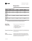
Table 46. Valves Closed
Probable Cause Explanation
Normal operation The valves open and close to meet unit capacity requirements.
unit disabled · The TUC may be disabled via the shutdown mode on a Tracer
®
system or if BIP1 is configured as external interlock.
· During the stop modes, the valves remain closed unless freeze
avoidance is enabled and the fresh air temperature falls
below the freeze avoidance setpoint (configurable).
· If the fresh air temperature falls below the freeze avoidance
setpoint, the valves open. The TUC enables freeze avoidance
whenever the freeze avoidance setpoint is not zero.
Override present The valves may be overridden to the closed position by either the
Tracer
®
system or by Everyware software. Whenever any override
is active, the TUC drives the valves closed unless they are concur-
rently overridden open.
Latching diagnostic presen A specific list of diagnostics effects valve operation. For more
information, see the Diagnostics section on page 73. Latching
diagnostics require a manual reset to restore normal unit operation.
Autocycle test The controller includes an autocycle test sequence that verifies
analog and binary output operation and associated output wiring.
However, based on the current stage in the test sequence, the
valve(s) may be closed. Refer to the Human Interface section on
page 62.
Maximum heating/cooling The Tracer
®
may limit the maximum heating/cooling capacity of the
capacity of zero TUC from zero to 100%. When the maximum cooling capacity is
zero, the cooling valve remains closed. When the maximum heating
capacity is zero, the heating valve remains closed.