


Terminal Unit
Control (TUC)
88 UNT-IOM-6
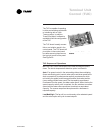
For TUC controlled units that will interface with the Trane Tracer
®
system or Tracer Summit
®
building management system, terminate
the communication wiring in the control box at the designated
terminals on the low voltage terminal strip. Reference the unit wiring
schematic or submittals.
Take care to maintain the correct polarity throughout the communica-
tion wiring circuit.
Ground shields at each TUC, taping the opposite end of each shield
to prevent any connection between the shield and another ground.
Refer to Trane publication, EMTX-IOP-1 Installation Operation and
Programming Guide, for the communication wiring diagram.
Communication wire must conform to the following specification:
· Shielded twisted pair 18 AWG
· Capacitance 23 (21-25) picofarads (pF) per foot
· Listing/Rating - 300V 150C NEC 725-2 (b) Class 2 Type
CL2P
· Trane Part No. 400-20-28 or equivalent, available through
Trane BAS Buying Group Accessories catalog
Follow these general guidelines when installing communication
wiring:
· Maintain a maximum 5000 ft. aggregate run
· Install all communication wiring in accordance with the
NEC and all local codes.
· Solder the conductors and insulate (tape) the joint suffi-
ciently when splicing communication wire. Do not use wire
nuts to make the splice.
· Do not pass communication wiring between buildings
because the unit will assume different ground potentials.
· Do not run power in the same conduit or wire bundle with
communication link wiring.
Tracer
®
Communication
Wiring