


UNT-IOM-6 23
4. Vent the vacuum breaker line to atmosphere or connect it into the
return main at the discharge side of the steam trap.
5. Pitch all steam supply and return mains down a minimum of 1 inch
per 10 feet in the direction of flow.
6. Do not drain the steam mains or take-off through the coils. Drain
the mains ahead of the coils through a steam trap to the return line.
7. Overhead returns require 1 psig of pressure at the steam trap
discharge for each 2-foot elevation to ensure continuous condensate
removal.
8. Proper steam trap selection and installation is necessary for
satisfactory coil performance and service life. For installation, use the
following steps:
a. Locate the steam trap discharge at least 12 inches below the
condensate return connection. This provides sufficient hydrostatic
head pressure to overcome trap losses and ensure complete conden-
sate removal.
b. Trane Company recommends using flat and thermostatic traps
because of gravity drain and continuous discharge operation.
c. Use float and thermostatic
traps with atmospheric pressure
gravity condensate return, with
automatic controls or where the
possibility of low pressure supply
steam exists.
d. Always install strainers as
close as possible to the trap inlet
side.
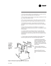
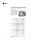
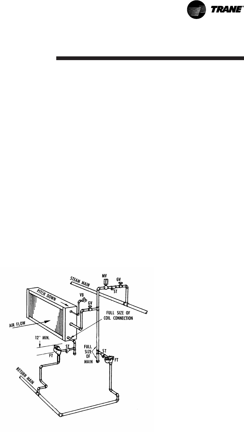
Reference Figure 8 for an ex-
ample of a properly piped steam
coil.
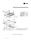
Figure 8. Example of typical piping to the steam coil.
ST = Strainer
FT = Float and
thermostatic
steam trap
MV = Manual
air vent
GV= Gate valve
VB = Vacuum
breaker, 15°
swing check
valve