


UNT-IOM-6 85
Tracer
®
ZN.520
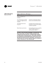
Table 35. Fan outputs do not energize
Probable Cause Explanation
Random start observed After power up, the controller always observes a random start from zero
to 25 seconds.The controller remains off until the random start time
expires.
Power up control wait When power up control wait is enabled (non-zero time), the controller
remains off until one of two conditions occur:The controller exits power
up control wait once it receives communicated information.The controller
exits power up control wait once the power up control wait time expires.
Cycling fan operation The controller operates the fan continuously when in the occupied,
occupied standby, or occupied bypass mode. When the controller is in
the unoccupied mode, the fan is cycled between high speed and off with
capacity.
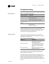
Unoccupied operation When the controller is in the unoccupied mode, the fan is cycled
between high speed and off with capacity to maintain zone temperature
control.
Fan mode off When a local fan mode switch (provided on the Trane zone sensor)
` determines the fan operation, the off position controls the unit off.
Requested mode off You can communicate a desired operating mode (such as off, heat,
and cool) to the controller. When off is communicated to the controller,
the unit controls the fan off. There is no heating or cooling.
Diagnostic present A specific list of diagnostics affects fan operation. For more information,
see the Diagnostics section.
No power to the If the controller does not have power, the unit fan does not operate. For
controller the Tracer
®
ZN.520 controller to operate normally, it must have an input
voltage of 24 VAC. When the green LED is off continuously, the control
ler does not have sufficient power or has failed.
Unit configuration The controller must be properly configured based on the actual installed
end devices and application. When the unit configuration does not match
the actual end devices, the valves may not work correctly.
Manual output test The controller includes a manual output test sequence you can use
to verify output operation and associated output wiring. However, based
on the current step in the test sequence, the unit fan may not be on.
Refer to the Manual Output Test section.
Unit wiring The wiring between the controller outputs and the fan relays and con
tacts must be present and correct for normal fan operation.
Troubleshooting