


16 UNT-IOM-6
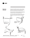
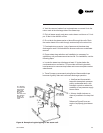
4. Insert the threaded rods or lag screws in the wall before setting the
unit in place.
5. Remove the front panel (cabinet unit only) by lifting it upward.
6. Position the hanger holes, located on the back of the unit, over the
rod or lag screw heads, pushing the unit downward to properly
position.
7. Complete piping and wiring connections, in addition to any neces-
sary ductwork to the unit as instructed in the following sections.
Ensure that the auxiliary drain pan is in position on fan-coil units.
8. Install the front panel before starting the unit.
On cabinet units, replace the front panel by aligning the bottom tabs
on the unit with the respective slots on the panel bottom. Align the
top edge of the unit with the panel.
On recessed units, install the front panel by aligning and locking
together the interlocking support channel of the panel and unit. While
holding the panel against the unit, tighten the screws at the top of the
panel until it fits tight against the units front. Do not over tighten the
screws.
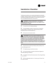
CAUTION: All unit panels and filters must be in
place prior to unit start-up. Failure to have panels and
filters in place may cause motor overload.
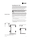
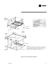
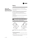
Install horizontal units suspended from the ceiling using the four 5/8
inch diameter double key slot hanger holes, located on the top of the
unit. The hanger holes allow a maximum shank size of 5/16 inch
diameter threaded rods or lag screws (installer provided). Follow the
installation procedure below.
Note: Follow the requirements of National Fire Protection Association
(NFPA) Standard 90A or 90B, concerning the use of concealed
ceiling spaces as return air plenums.
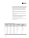
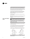
1. Prepare the ceiling opening for recessed units. Reference the unit
submittals for each unit size dimensions.
!
Horizontal Units